I looked at your Bode plots. Great! Nice job. That notch 2 MHz is weird. What's causing that? Or rather, how can we get rid of it?
Not sure what's really causing it, but it's definitely affected by several things, including the global feedback compensation, the output L/R and other such things.
While trying things to tweak it, I was able to totally eliminate that, at the cost of much less bandwith and the phase margin was still not coming together.
Each added stage adds phase shift, and the power types are the worst.
Right, I didn't even think about that, and I am fighting too much shifting, which makes it quite hard to get a reasonable margin. And it always comes at the expense of things like distortion and bandwidth.
I suggest simplifying the output section to a double, not a triple. Without the MJE340/350, we have more than enough drive from the VAS (Up to 75ma drive current to a transistor with a beta of 100+ which is current limited to 3A by the emitter resistor). Does that make sense?
I agree, this might make it more stable and easier to compensate and finally get that margin we need.
I'm not sure how much of my latest schematic you will simulate.
Well, most of it of course. I only leave out the things that aren't quite a true part of the amp, like the regulators for example. I just simplify with voltage sources.
Of greatest interest to me is the effect of VAS negative feedback. I'd also like to see the effect on stability of reducing the output from triple to double.
I'll have to make some more sim runs to show what we've been having so far.
Then we'll go on to those latest changes and compare.
What do you think?
A load of fun, and quite interesting. Let's get this done all the way and make a nice diy build.
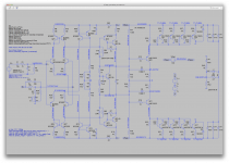
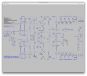
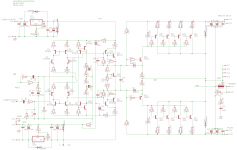
In the attached schematic, the only change is the divider network to the output stage, to higher impedance load for the VAS. Hopefully that gets the Vbe multiplier to adjust.
This looks like the previous post, I'm not really seeing much difference, except perhaps for diodes taken out.
Changes are always messy. I hope we can zero in and freeze it.
I think we're getting fairly close to that now. We've had a few breakthroughs and got it actually running. Which is so much better than my early attempts using qsc's schematics. It feels like they have some voodoo going on to make their things work. And they do work well too.
Have you thought about heatsinking, packaging and the like?
Not so much, so far, because I was more into making it work and not yet putting too much thought in a build.
But one thing is certain, the sink can be smaller than other ordinary builds.
Personally I don't like having all the power trannies on the same side of the pcb, but it depends.
Choosing a heatsink can depend on the end goal and then it will obviously affect layout.
I think if the goal is a simple module to put in an active speaker cabinet, like for example a bass cabinet where we put the amp vertically on its backside, a fairly flat and wide sink would do, with the fins vertical and the other side totally flat so the amp comes right on that flat side with 2 rows of power trannies mounted vertically. That is one case where having 2 rows on opposite sides of the pcb is a must, and to keep things easy to mount, the trannies should come out on the side for easy mounting. This is a quite common scheme used out there, but I favor this only if the whole thing is made vertical and the natural convection works properly without having one side warmer than the other.
I'm saying this because some people do this kind of layout, but the sink is not vertical and they put one side of the power trannies at the bottom while the other is at the top, which makes for the lower side being cooler than the other. Not symmetric.
It bears on board layout, which I am already thinking about. If we put 8 outputs on one side, it's long and thin. Say 2x5 ish. Let's you mount the board at right angles to the HS. Fits most situations. First photo below shows a bizarre layout with 8 outputs, mounted 4 per side of the board. An actual production board, odd layout. The alternative is an even longer board for all that stuff.
If the goal is making a mono-block amp, then it's possible to use the same pcb layout but using 2 sinks, one on each side.
I am fond of those heatsinks from conrad:
Conrad Heatsinks - Products
But there is one big drawback that I don't like at all with this, is the fact that having only a single transistor sensing the sink's temp for bias regulation, implies that only one side gets sensed. Not good I think.
If we put 4 on opposite sides, they can bend down or mount co planar with the board, depending on heat sink.
Yes, I like that, but it does have that drawback as I just mentioned above.
How do you choose which side to sense? No way, you can't. It should be both sides, but there is only one device sensing...
If we can find a sensible way to solve this, it would be a very nice option.
This is good for big plates like inside a sub, or long channel heat sinks, say. A trial layout in picture 2 of something else, 8 outputs.
Yes, maybe something like I described, as a module, to mount vertically with the fins convecting vertically. If on a single sink, then the bias sensing tranny can mount in a somewhat "neutral zone", which senses both sides.
Something to think about some more.
One thing seems to be implied. Those amps don't seem to be suited for sharing the same psu for 2 channels, so that obviates using 2 totally separate psus, and that means basically 2 mono amps in a stereo box if the goal is making a stereo amp.
I would more favor a single amp, in a mono-block fashion...
I think we're getting fairly close...
One thing seems to be implied. Those amps don't seem to be suited for sharing the same psu for 2 channels, so that obviates using 2 totally separate psus, and that means basically 2 mono amps in a stereo box if the goal is making a stereo amp.
I would more favor a single amp, in a mono-block fashion...
The power transformer is no problem. If you use power transformer, it just needs two secondaries isolated. Zillions of those. Secondaries just float, independently.
As an example, consider the usual so-called isolation transformer, super common surplus. These are used to convert from 110 to 220 and are available in a wide range of wattage. If you wire the primaries for your local voltage, you have two isolated secondaries of 110vac, which after full wave rectification become something between 154v and 168v floating dc, depending on your line voltage at the moment, which typically can range from 110 to 120. That gives you a floating dc in the range of +-77 to +-84v. If you use a common Kilowatt size, you have enough power for two 500w amps. These are not cheap, but they are readily bought.
If you have a high current low voltage supply, you can use a voltage doubler to rectify the secondary to something suitable. Say you have a transformer with 48vac, common for telecom. Rectifies to about 138 vdc via doubler, or +-69v. This is an uncommon approach, but would work fine.
If you have a burned out high power amp, the transformer will probably have a center-tapped secondary that you can use, ignore the center tap.
Or you can use a switcher if it allows you to float the DC.
There are many options, when the time comes.
I said:
In the attached schematic, the only change is the divider network to the output stage, to higher impedance load for the VAS. Hopefully that gets the Vbe multiplier to adjust.
Spookydd said
This looks like the previous post, I'm not really seeing much difference, except perhaps for diodes taken out.
So I say: Yep, diodes removed, resistor value increased to make it about what I recall worked. The only change, to get the Vbe multiplier to work, or rather to adjust.
Spookydd said: But there is one big drawback that I don't like at all with this, is the fact that having only a single transistor sensing the sink's temp for bias regulation, implies that only one side gets sensed. Not good I think.
I say: The P side will be warmer, we can sense it alone. If you are really concerned, use the ON Semiconductor transistors with a sense diode built in. You could maybe just use one per side, say the hottest of the bunch, then add the diodes in some way and you are sensing both sides. http://www.onsemi.com/pub_link/Collateral/AND8196-D.PDF
I say: The P side will be warmer, we can sense it alone. If you are really concerned, use the ON Semiconductor transistors with a sense diode built in. You could maybe just use one per side, say the hottest of the bunch, then add the diodes in some way and you are sensing both sides. http://www.onsemi.com/pub_link/Collateral/AND8196-D.PDF
The power transformer is no problem. If you use power transformer, it just needs two secondaries isolated. Zillions of those. Secondaries just float, independently.
Sure you can use a dual secondaries, and they don't even need a center tap, which is one advantage as well, but by sharing the same transformer for 2 amps, it's inevitable to have some influence from one to the other, so why not go the extra mile and separate completely? Less cross-talk and drooping rails...
Besides, single secondary transformers are usually less expensive.
What's the cost difference between a 1kva dual 85v secondaries compared to 2 500va ones with only a single 85v??? Maybe something to look at.
Since everything must be separated from the secondary, then why also share the magnetic core and primary?
Well, that's up to the builder and that can be a simple choice to make at build time that doesn't involve much.
Personally if I can separate, I do it.
As an example, consider the usual so-called isolation transformer, super common surplus. These are used to convert from 110 to 220 and are available in a wide range of wattage. If you wire the primaries for your local voltage, you have two isolated secondaries of 110vac, which after full wave rectification become something between 154v and 168v floating dc, depending on your line voltage at the moment, which typically can range from 110 to 120.
That's a good idea to wire the transformer, for those who want to attempt it.
I did this many times long ago and got good transformers that were customized to what I really wanted. We can even oversize the secondary wires for less series resistance and less droopy power...
But diyers are not all from the same part of the world and the availability of those base transformers to rewind may not be always that good.
For example in the usa there are always good places to go for surplus, but that's not the case everywhere, and without such sources, it may be a problem finding the right stuff to work on.
For example I used to go to a place called "skycraft" in winterpark florida, which has boat loads of good and varied surplus stuff. A real gold mine for diyers. Alibaba!!! But can't find anything even close to that where I am currently located (france) and can't find anywhere something I could work on.
We have fellow diyers all over the place, and some even have troubles getting certain electronic parts. People in the philippines, india, etc...
That gives you a floating dc in the range of +-77 to +-84v.
I haven't even tried yet to raise the rail voltage beyond the 60v that we've been on for sims. This might be a thing to try out once we have a good working sim.
Since the power trannies are quite capable of handling much higher voltages that 120v, this could easily be done.
If the rails go higher and we want to stay in the soa, we can always add more pairs of O.Ds and make quite powerful amps.
One question is, when upping the rails much more, do we have enough drive from the vas to drive that all the way?
If you have a high current low voltage supply, you can use a voltage doubler to rectify the secondary to something suitable. Say you have a transformer with 48vac, common for telecom. Rectifies to about 138 vdc via doubler, or +-69v. This is an uncommon approach, but would work fine.
Definitely something for the diyers to look at when gathering their stuff. Those things can easily be customized without changing the amp's design. Good to have flexible options.
The single winding feature for the amp does make things easier.
There is one thing I'd like to know more about. How to simulate the ferrite beads.
If this works really well to stop oscillations and allows using smaller caps or none at all in some spots, it would be beneficial.
How much distortion introduction can we expect from using that instead of compensation caps, or larger ones?
What's the effect on phase shift?
Can we just put a small value res in series with a tiny coil?
This deserves exploration.
Ferrite Bead Spice Models
Spookydd said "There is one thing I'd like to know more about. How to simulate the ferrite beads.
If this works really well to stop oscillations and allows using smaller caps or none at all in some spots, it would be beneficial.
What's the effect on phase shift?
Can we just put a small value res in series with a tiny coil?
Spookydd said "There is one thing I'd like to know more about. How to simulate the ferrite beads.
http://www.murata.com/en-us/tool/sparameter/ferritebead
http://www.diyaudio.com/forums/software-tools/249548-spice-models-murata-ferrite-beads.html
https://product.tdk.com/info/en/technicalsupport/tvcl/general/beads.html
http://www.diyaudio.com/forums/software-tools/249548-spice-models-murata-ferrite-beads.html
https://product.tdk.com/info/en/technicalsupport/tvcl/general/beads.html
If this works really well to stop oscillations and allows using smaller caps or none at all in some spots, it would be beneficial.
Nelson Pass used to highly recommend them for placing directly on the gate leads of MOSFETs. That seems to have been forgotten. I have seen them at 60MHz, scary. So for me they are standard practice on Mosfet gates. But I believe Miller caps on the VAS must be our first line. Then the other strategic points can be tried. Adding an RC across the collectors of the differential amp, and RC from VAS collectors to the NFB point are the next two common approaches, with restraint.
How much distortion introduction can we expect from using that instead of compensation caps, or larger ones?What's the effect on phase shift?
Can we just put a small value res in series with a tiny coil?
I suspect they model as small inductance in series with small resistance. Look at the models I posted earlier. Here are more:
Ferrite Beads Demystified | Analog Devices
http://www.analog.com/media/en/technical-documentation/application-notes/AN-1368.pdf
Ferrite Beads Demystified | Analog Devices
http://www.analog.com/media/en/technical-documentation/application-notes/AN-1368.pdf
I'm not sure how much of my latest schematic you will simulate. Of greatest interest to me is the effect of VAS negative feedback. I'd also like to see the effect on stability of reducing the output from triple to double. My other changes are known to work well, so not of as much concern.
What do you think?
In the attached schematic, the only change is the divider network to the output stage, to higher impedance load for the VAS. Hopefully that gets the Vbe multiplier to adjust.
Ok, I made the sim from the last 2.9.8.3 version, and the bias spreader doesn't work.
There are several volts of rail offset, but we can't know for sure what it will be once the bias is set properly. But I suspect we may need to have an adjustment to the offset. This can easily be done without altering the schematic as it is now, by just adding a divider to force the in- a tiny bit, like I did in y tests. This works well and the "force" applied isn't much, at most a few mV.
This stuff about the ferrite beads in interesting, and once we get this one up and going, it would be a good time to tried them out.
Attachments
...the bias spreader doesn't work.
....
Hmm... So the divider on the driver bases wrong value I guess. For now just remove the 1.2k resistors across the driver bases. That seems to work ok in your implementation, no? The bias spreader should have enough adjustment range then. We need 2x Vbe plus 10% to turn on the drivers, my guess, but lets figure that out later.
We need to be working on stability for this modified input stage, so bypass this roadblock for now. I suspect that with more gain it will sing more. I'm curious whether we just end up with a monster Miller cap, that's OK with me really if we get it stable. The other caps you sprinkled, RC on the input collectors, or??
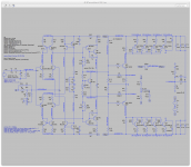
Alright, I found out one thing that was causing it not to work in the previous post.
My mistake, when I removed the pre-drivers, I forgot to swap the driver's positions.
Anyway, it's tricky to get the bias set, and without a sufficient offset correction, impossible.
So I added an offset correction divider on the in- as I mentioned, and although it requires a somewhat overly "energetic" correction, it does correct the issue and balance it out.
One thing to note is how very dependent the bias and offset adjustments are to each other, and the range of adjustment is rather narrow, so we get a full swing to either rail if we get too far from optimum adjustment. This would mean "watch out" when doing this for a diyer.
I only saw my mistake on the drivers when I separated the power half from the rest, and I saw how the vas bias current was far too high, so I had to adjust its load resistors and got it down to about 22mA.
Once that was done, the bias and offset became adjustable, although tricky, and I got it well balanced.
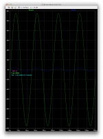
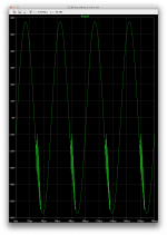
This didn't allow it to work right in a transient analysis though, as we had loads of oscillations as is.
So I tweaked the compensation and got it to work about right, even at 20khz, as shown in the shots attached, with fairly decent thd.
My mistake, when I removed the pre-drivers, I forgot to swap the driver's positions.
Anyway, it's tricky to get the bias set, and without a sufficient offset correction, impossible.
So I added an offset correction divider on the in- as I mentioned, and although it requires a somewhat overly "energetic" correction, it does correct the issue and balance it out.
One thing to note is how very dependent the bias and offset adjustments are to each other, and the range of adjustment is rather narrow, so we get a full swing to either rail if we get too far from optimum adjustment. This would mean "watch out" when doing this for a diyer.
I only saw my mistake on the drivers when I separated the power half from the rest, and I saw how the vas bias current was far too high, so I had to adjust its load resistors and got it down to about 22mA.
Once that was done, the bias and offset became adjustable, although tricky, and I got it well balanced.
This didn't allow it to work right in a transient analysis though, as we had loads of oscillations as is.
So I tweaked the compensation and got it to work about right, even at 20khz, as shown in the shots attached, with fairly decent thd.
Attachments
Hmm... So the divider on the driver bases wrong value I guess.
Actually no. As it turns out, as you see in my previous post, it was the vas bias current being far too high.
Reducing that made it possible to adjust and balance out, but not without the offset divider correcting the centering.
For now just remove the 1.2k resistors across the driver bases. That seems to work ok in your implementation, no?
I'll try that just to see what happens, but that wasn't necessary after I adjusted the vas loads.
We need to be working on stability for this modified input stage, so bypass this roadblock for now.
I think I pretty much did, without touching those driver bases res.
I suspect that with more gain it will sing more. I'm curious whether we just end up with a monster Miller cap, that's OK with me really if we get it stable.
Actually not at all, it's the opposite, to stabilize it, I had to drstically reduce the miller cap as well as the global feedback one.
The other caps you sprinkled, RC on the input collectors, or??
Didn't need to do this on this one.
But the only sims I ran beside the operating point so far, are transient, so I don't even have a bode plot yet for ac analysis, and nothing beyond that. We'll have to look at other things later. Feeding it square waves, check the TIM, noise, pssr, etc...
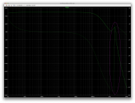
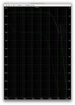
Here is a plot from the ac analysis as it stands right now as shown on my previous post. No changes to any values, just ran the ac.
This is showing the same kind of erratic phase shifting in the 2mhz area...
Phase margin reads great but it's not really right, because it comes out right at unity gain right after a huge reversal of phase shift, which I don't think is ok.
This is showing the same kind of erratic phase shifting in the 2mhz area...
Phase margin reads great but it's not really right, because it comes out right at unity gain right after a huge reversal of phase shift, which I don't think is ok.
Attachments
I forgot to move the zobel to the amp output from the speaker output, but when I moved it, oscillations that weren't there came again. Trying to tweak compensation to keep that out now.
I do see what you mean, VAS current too high. You had to adjust the emitter resistors to 390. That does reduce the gain of the VAS.
I see I goofed to cause that. All my thinking assumed 2v at the VAS base, but we have closer to 3.5v probably, which makes VAS current high. I just put 68 ohm resistors on the current mirrors by habit, but they should be lower for the high tail current, and I forgot the slight drop across the new power filter of 25mv. Let's still aim for ~2v at the VAS base, so maybe drop the 68ohm resistors to 22 or so. What is the voltage across the mirror transistor, about 1.3v? That would total 2.2v, roughly, including the filter voltage drop. Maybe the VAS emitter resistors need to be about 47-68 ohm then, about where we started. Make any sense to you?
I see I goofed to cause that. All my thinking assumed 2v at the VAS base, but we have closer to 3.5v probably, which makes VAS current high. I just put 68 ohm resistors on the current mirrors by habit, but they should be lower for the high tail current, and I forgot the slight drop across the new power filter of 25mv. Let's still aim for ~2v at the VAS base, so maybe drop the 68ohm resistors to 22 or so. What is the voltage across the mirror transistor, about 1.3v? That would total 2.2v, roughly, including the filter voltage drop. Maybe the VAS emitter resistors need to be about 47-68 ohm then, about where we started. Make any sense to you?
I do see what you mean, VAS current too high. You had to adjust the emitter resistors to 390. That does reduce the gain of the VAS.
Yes, I didn't touch the ltp and mirrors. This worked, but may not be optimal for other reasons.
Let's still aim for ~2v at the VAS base, so maybe drop the 68ohm resistors to 22 or so. What is the voltage across the mirror transistor, about 1.3v? That would total 2.2v, roughly, including the filter voltage drop. Maybe the VAS emitter resistors need to be about 47-68 ohm then, about where we started. Make any sense to you?
Alright, I'll try this out now.
But in the mean time, here is something more about what I've been doing lately.
I disconnected the driver based divider, and we seem not to need that.
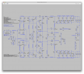
I tried disconnecting the input filter cap to see what would happen to that spike we have around 2mhz, and of course it goes way up.
I tried several lower values of that filter cap, looking at what happens, but it wouldn't help enough.
With it back on and at 1n, we have that spike at 2mhz above the unity gain (see plot annotations). It might be good to push that beyond and below the unit gain, so that huge phase reversal happens below unity gain.
Attachments
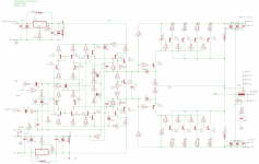
Ok, lowering the mirror loads to 22, but the vas loads still needs to be something like at least 270 to keep vas bias down to about 25mA.
Keeping the driver base divider out for now.
Well balanced, but as you can see, we have oscillations back.
I'll see about stopping them now.
Keeping the driver base divider out for now.
Well balanced, but as you can see, we have oscillations back.
I'll see about stopping them now.
Attachments

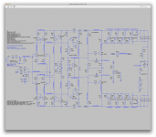
Just so we're in sync, I put in the 22 ohm resistors, and the 270s.
I'd like to understand why the corner frequency moved down a little, and why the bizarre hook back on gain and phase got worse. Was it due to the front end mods, or removing the MJE340/350s? Or what else?
I'd like to understand why the corner frequency moved down a little, and why the bizarre hook back on gain and phase got worse. Was it due to the front end mods, or removing the MJE340/350s? Or what else?
Attachments
- Status
- Not open for further replies.
- Home
- Amplifiers
- Solid State
- grounded collector amp