These are critical but not a problem.
For example, the open loop output impedance may be more - but there is more feedback available because the CE OPS has gain.
First wizard rule - all gain stages must be in a completely greenhouse conditions. I.e. constant voltage or constant current, minimal parasitics, as active as possible and constant load, matched input-output impedances, etc.
With CE you will load high-current high-frequency gain stage to a dynamical system with complex impedance and the more bad - having intrinsic sources of EMF (moving mass with coil in field).
May be this will work in a labour conditions to a resistive load, but what about real field? Are you really rely on a feedback depth?
Here is a link that shows what I believe is reasonable with an Eimtter Follower OPS
I am happy with that result but perhaps a CE OPS can do better.
So you can think about that, while I think of a detailed reply to your post😉
Curves of the pretty stable amp.
🙂
Pros:
1. Huge phase margin, nowhere under 180 degree, very safe "higher 90 degree" at the 0 dB point.
2. Huge gain margin, about 40 dB at "near 180 degree" point.
3. Good low-freq depth, about 90-96 dB at a higher corner of audioband. So with using of OPS with something near 1% THD (-40 dB of second harmonic) it will produce a real pretty amp, having under straight measuring ~-130:140 dB overall THD.
Cons:
1. You can place your Zero even higher, why you fear to drop phase under 180 degree? At a frequency range, where we have more than +10 dB gain we can doesn't care where phase is. The first boundary to care is a point of gain at +10 dB, we must return phase here to no less than 150 degree value. The second boundary is a point of -10 dB gain, the phase here must be again at no less than 150 degree. In the range of {+10 : -10} of the gain the phase must not be lower than 150 degree. Thats all.
2. Higher gain boundary (at -10 dB gain) placed at about 60 MHz, just let me know about your OPS devices which can do this. AFAIK, cascodes can do this and TO-220 devices can do this, so with medium complexity (3pairs) you will be limited with 1-2 Ampere of load current.
3. All TO-247/264 (+MT-200) power devices has a very bad fT dependance of flowing current, being dynamical subsustem with gain and complex load this can cause feedback loop to be breaked/opened. As you can guess - with very, very bad results.
4. Such an amp must be equipped with output filter, just because ~2-3 meter wires will be not good, but no more no less an radiating antenn with unpredicted impedance.
5. What is a noise level at the output with shorted input? ~50 microvolts? So why you want -130 dB THD? SINAD at 1-10 W (the most interested power) will be pretty limited at ~80-90 dB just by noise component. Yes, noise are uncorrelated with the signal, but i would prefer comparative values of the components. Do not drop one to -130 with second staying at -80, try to make both at -100.
What we can do?
1. Drop low-freq amplification to near 60 dB with staying at current correcting scheme (nominals must be corrected).
2. Move zero higher with allowing phase to go under 180 degree (elsewhere you have more +10 dB gain) with lowering loop closing frequency.
3. Place second zero and third pole.
4. Move first pole lower.
Goals:
1. Have ~-120 THD (no matter, ~40 dB feedback depth with -80 dB THD OPS or 80 dB feedback depth with -40 dB THD OPS)
2. Have ~3-4-5 MHz loop-closing freq
3. Have as low as possible input-referred noise, balance it with THD/gain/depth
With your upper Frequency order we can do something like this:

This is the plot of the headamp with a pair of AD8065 at the input and LME49610 at the output. PSRR at the both supply rails at an order of 90 dB around whole audioband.
Last edited:
...If the lack of a deterministic formulation of the Barney optimal bias point...Use mosfets instead 😀
The lack of an optimal bias point formula isn't a major problem, just wanted to check it wasn't already solved.
It is an easy piece to simulate, will do that soon, I suspect the optimum will be essentially equivalent - Bias current to keep 26 mV across the emitter resistors.
I also expect the CE won't be worse than EF for crossover distortion, may be better.
Seems there should be an obvious answer, but I can't see it yet.
Mosfets look like they will be ideal for this circuit, will check it out for sure.
Best wishes
David
Ok, both replies in one.
Not necessarily, if the OPS is minimum phase then we can compensate for any roll off.
That is basically what an EF does anyway, it "looks" faster but it's the same transistor.
I don't think this is necessary, but it is sufficient.
My view that once we have sufficient open loop gain to have the 20 kHz that we want then there is little point to add more from DC to 20 Khz.
I think of this as an approximation of the Bode Maximum Feedback.
Nyquist shows us how to do tricks like ensure stability even with time delays and beat the usual 2 pole slope limit.
But ultimately we must have loop gain, which means power gain.
No way round this.
Sensible questions, my simulation shows what I believe is reasonable.
Details are in specific response below.
Because "Unconditionally Stable" sounds better😉
Of course we can drop the phase even further and increase the feedback even more but I see little point - the distortion is already far less than any audible requirement.
And once we have conditional stability then we have to worry how the amp will behave as it powers up, powers down and if it clips.
So I choose to draw the line at that point, keep the amp unconditionally stable.
The faster of the plots is for the inner nested loop.
The Thermal Trak Output transistors from OnSemi were used in the simulation and they are not too bad for fT depependence.
And because I have unconditional stability I am less concerned about whether the feedback loop is broken/opened because it will not cause the bad results you warn of.
Of course I don't want the amp to clip, in fact I have very efficient speakers and this is not a problem in practice.
Yes, this is true, my simulation has one and I would surely do this on any real amplifier.
The amp is intended to directly connect to very efficient compression driver so I have taken considerable effort to minimize noise.
So noise is <5 microvolts approximately, and in balance with the THD.
Actually the amp is intended to incorporate equalization for the compression driver so the noise specification is not simple but it's about 1 nV/rt Hz input referred.
Equal to just less than 5 microvolts output for a flat amplifier of typical gain.
Also the distortion is not quite as low as you estimate, there are load effects between the sections so it is not just a simple "divide by 1 plus loop gain".
Ed Cherry discusses the theory for this and I have seen the effect, but I find it simpler to just run the simulation and check the number.
I think the extra information I provided above shows that we have similar objectives of balanced performance, and that I have already achieved this objective😉
My main objective now is to make it simpler, the low noise circuit does mean a few extra transistors.
The IPS runs heavy current, for obvious reasons, that makes input bias currents more than usual, the low feedback resistance would lead to input offset if not taken care of, and so on.
Best wishes
David
1. We must start from the OPS pole.
Not necessarily, if the OPS is minimum phase then we can compensate for any roll off.
That is basically what an EF does anyway, it "looks" faster but it's the same transistor.
we want to have constant feedback depth (and may be phase) all around audioband.
I don't think this is necessary, but it is sufficient.
My view that once we have sufficient open loop gain to have the 20 kHz that we want then there is little point to add more from DC to 20 Khz.
3. Next with your choise of 2p+1z we just need to make mathematical criteria, which would allow to maximize band with -40 dB/decade slope. This provide mathematically optimized frequency point to place our zero.
I think of this as an approximation of the Bode Maximum Feedback.
... stable systems under Niquist criteria.
Nyquist shows us how to do tricks like ensure stability even with time delays and beat the usual 2 pole slope limit.
But ultimately we must have loop gain, which means power gain.
No way round this.
1. What amout of feedback depth at 20 kHz you want to achieve?
2. What Ft can you provide?
3. What PSRR of your supply are?
4. What input noise/resistance can you provide?
5. What closed-loop gain do you want?
6. What THD do your naked OPS have?
And then we can discuss much more clearly.
Sensible questions, my simulation shows what I believe is reasonable.
Details are in specific response below.
1. You can place your Zero...why you fear to drop phase under 180
Because "Unconditionally Stable" sounds better😉
Of course we can drop the phase even further and increase the feedback even more but I see little point - the distortion is already far less than any audible requirement.
And once we have conditional stability then we have to worry how the amp will behave as it powers up, powers down and if it clips.
So I choose to draw the line at that point, keep the amp unconditionally stable.
2. ... boundary (at -10 dB gain) placed at about 60 MHz, just let me know about your OPS devices which can do this. AFAIK, cascodes can do this and TO-220 devices can do this, so with medium complexity (3pairs) you will be limited with 1-2 Ampere of load current.
The faster of the plots is for the inner nested loop.
3. All TO-247/264 (+MT-200) power devices has a very bad fT dependance of flowing current, being dynamical subsustem with gain and complex load this can cause feedback loop to be breaked/opened.
The Thermal Trak Output transistors from OnSemi were used in the simulation and they are not too bad for fT depependence.
And because I have unconditional stability I am less concerned about whether the feedback loop is broken/opened because it will not cause the bad results you warn of.
Of course I don't want the amp to clip, in fact I have very efficient speakers and this is not a problem in practice.
4. Such an amp must be equipped with output filter, just because ~2-3 meter wires will be not...
Yes, this is true, my simulation has one and I would surely do this on any real amplifier.
5. What is a noise level at the output with shorted input? ~50 microvolts? So why you want -130 dB THD? SINAD at 1-10 W (the most interested power) will be pretty limited at ~80-90 dB just by noise component...
The amp is intended to directly connect to very efficient compression driver so I have taken considerable effort to minimize noise.
So noise is <5 microvolts approximately, and in balance with the THD.
Actually the amp is intended to incorporate equalization for the compression driver so the noise specification is not simple but it's about 1 nV/rt Hz input referred.
Equal to just less than 5 microvolts output for a flat amplifier of typical gain.
Also the distortion is not quite as low as you estimate, there are load effects between the sections so it is not just a simple "divide by 1 plus loop gain".
Ed Cherry discusses the theory for this and I have seen the effect, but I find it simpler to just run the simulation and check the number.
What we can do?...
I think the extra information I provided above shows that we have similar objectives of balanced performance, and that I have already achieved this objective😉
My main objective now is to make it simpler, the low noise circuit does mean a few extra transistors.
The IPS runs heavy current, for obvious reasons, that makes input bias currents more than usual, the low feedback resistance would lead to input offset if not taken care of, and so on.
Best wishes
David
Last edited:
5µV output noise is equivalent to Ein = 1.69nV/rtHz for an amplifier with a gain of 20times (+26dB).
Is under 2nV/rtHz achievable in a power amplifier?
Is under 2nV/rtHz achievable in a power amplifier?
Yes, as long as you are willing to drive its input from a low impedance (50 ohm) source.Is under 2nV/rtHz achievable in a power amplifier?
Many power amps can be and are driven from 50ohms sources.
But are any of these amps achieving Ein<2nV/rtHz?
D.Self gives a few lower noise power amplifier proposals and he gets down to around -96dBu (~12uV output noise). That's still a lot more than <5uV
But are any of these amps achieving Ein<2nV/rtHz?
D.Self gives a few lower noise power amplifier proposals and he gets down to around -96dBu (~12uV output noise). That's still a lot more than <5uV
Is under 2nV/rtHz achievable in a power amplifier?
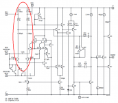
Try this frontend:

LSK170 at the input, BC550c as cascodes.
Does that have some features specifically to achieve exceptionally low noise?
Yes, that's little improved AD797 schematic, where first stage R2 and R3 was replaced by current sources for better isolation from upper rail.
Use something like this, but with additional RC-filtration between diodes and bases.

Although 2nV/rtHz input voltage noise in an audio power amplifier is achievable, nobody has sold one (that I'm aware of). Because there is no demand for that type of product. A sufficiently talented and motivated DIYer could certainly build one as a technical curiosity, and establish a new benchmark, for bragging rights.
...Is under 2nV/rtHz achievable in a power amplifier?
Yes, exactly as Mark says, it's achievable but unavailable AFAIK.
To directly power compression drivers requires an amp far quieter that typical applications, so it's not just to boast.
And, as Pavel has recommended, I want balanced performance.
My compensation technique produces exceptionally low distortion so I tried to match this with equally exceptional low noise.
It would be nice to boast "quietest power amplifiers in the world" but I expect someone has already achieved < 2 nV / rt Hz.
An AD797 has ~1 nV / rt Hz by itself, should be possible to achieve < 2 total, if sufficient care was taken of the other contributors, especially feedback network.
Best wishes
David
Does that have some features specifically to achieve exceptionally low noise?
No emitter resistors on the LTP.
The trade-off is normally that this reduces the slew rate in a typical Miller compensated amp.
But I don't use Miller compensation, so I use considerably lower Re to reduce noise and still have excellent slew rate.
Contrary to usual expectation, this can also actually reduce distortion, if you know how to use it.
Best wishes
David
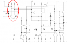
...With CE you will load... to a dynamical system with complex impedance and the more bad... intrinsic sources of EMF...mass with coil in field).
I have seen this claim often but I think it is a misconception.
Yes the coil moves in the field, and there are masses and EMF and so on.
But all this is taken into account by the electrical to physical transformation and the physical to acoustic transformation.
So that EMF that moves with a mass is transformed into an electrical capacitance, and similarly with the other elements.
The acoustical-mechanical system still looks like a passive network from the speaker terminals.
Probably more likely to have evident non-linearity but not any difference in behaviour from an equivalent electrical network.
May be this will work in a labour conditions to a resistive load, but what about real field? Are you really rely on a feedback depth?
Partly answered by your own next observation.
Curves of the pretty stable amp.
Firstly I wanted to show that it was possible to have compensation with much more feedback and still have PM and stability equal to simple Miller compensation.
This excellent stability does allow for unexpected real world conditions so I think I should be OK.
Also, I have modeled the amp with a variety of loads, capacitive, unloaded etc.
It is almost scary how quickly the PM can be reduced, so the apparently over cautious, conservative stability is actually quite reasonable.
Best wishes
David
...
Originally Posted by BesPav View Post
we want to have constant feedback depth (and may be phase) all around audioband.
I don't think this is necessary, but it is sufficient.
My view that once we have sufficient open loop gain to have the 20 kHz that we want then there is little point to add more from DC to 20 Khz.
...
David
I'm very surprised to hear this from serious students of audio amplification - commercial music audio signal, human perception and global feedback effect on errors by frequency component all make "flat feedback over audio bandwidth" a dubious prescription
several papers surveying "music" suggest a Power Bandwidth of only 3-5 kHz, rolling off above
common musical instruments, voice have fundamentals substantially below even 3 kHz
Human hearing Critical Bands are ~ log Frequency spaced, fewer above that 3-5 kHz music signal power bandwidth than below
Global Feedback reduces errors by the amount of excess loop gain at the Frequency of the error component
Global feedback reduces signal level in early stages (reducing their distortion products), again by the amount of feedback at the signal frequency – which can be the more important distortion reducing mechanism for 3rd order and above distortion – like the typical bjt diff pair tanh function that is “outside” the feedback loop
IMD difference components can be clearly audible with multitone tests like 1:1 19+20 kHz 1 kHz difference - and more feedback at 1 kHz does reduce the 1 kHz IMD component vs "flat feedback" by the factor of ~ 20 expected if a 1st order global feedback slope down to few hundred Hz is allowed
putting the above together suggests to me strongly weighting, allocating more distortion reducing feedback down to at least 3 kHz vs "flat below 20 kHz"
because Psychoacoustics such as Critical band density, noise floor suggest human hearing is far more sensitive to errors below 3-5 kHz than above
because there's substantially more music signal amplitude lower down than 20 kHz
because there's additional IMD error product frequencies that fold down to our more acute hearing range
and because it “costs” practically nothing in stability margin
Last edited:
Since US Patent 4,287,479A (link) has expired, you can freely use that trick to simultaneously get high slew rate AND low noise.
Or you can do what the NE5534 and its sub-1-nV descendant the LT1028 does: build a plain ordinary long tailed pair without emitter degeneration, but use resistor loads instead of a current mirror load.
I think you could fairly easily build a gain-of-10 front end PCB, running from ±25V supplies, that achieved 1nV/rtHz when driven from a low impedance source. Call that board "the input receiver" and mount it inside a power amplifier chassis. Now build a conventional power amp PCB in the same chassis, knowing that it's going to be driven from a super low impedance source: the front end PCB. Pay some attention to the noise performance of the conventional power amp, make sure its feedback divider Thevenin resistance is below 40 ohms, and Bob's your uncle.
Attachments
I'm very surprised to hear this from serious students of audio amplification... human perception and global feedback effect on errors by frequency component all make "flat feedback over audio bandwidth" a dubious prescription...
Hi JC
I don't doubt that humans are more sensitive to distortion at middle frequencies.
And if we built amps to only just exceed the detectable threshold of distortion then it would be desirable to increase the feedback at middle frequencies.
But seriously, who builds amps like that these days?
Maybe back when each individual tube was a substantial fraction of a day's pay?
Now we just specify a distortion number comfortably less than any plausible detection threshold.
So there is little point to increase it even further in the mid-band.
But nice to have your attention, can you comment on my initial query - do you know of any analysis or information on CE OPS?
Best wishes
David
I'm very surprised to hear this from serious students of audio amplification - commercial music audio signal, human perception and global feedback effect on errors by frequency component all make "flat feedback over audio bandwidth" a dubious prescription
Hi, JC, thank you for your attention!
I'm too very pleased!
I'd show plot with more than 140 dB depth at low-audioband and ~120 at 20 kHz. If we replace an LME49610 with properly tuned cascode MOSFET OPS, having something near 0,1% distortion figure, than we will anyway exceed dynamic range of any classic measurement setup. We just can't find the signal generator of that THD level.
If you offer some kind of Distortion Magnifier, than i will open my desk with another compensation scheme, having ~150 dB depth at 20 kHz.
Anyway unmeasurable.
So, really, the one thing to worry about - is the noise.
Human hearing Critical Bands are ~ log Frequency spaced, fewer above that 3-5 kHz music signal power bandwidth than below
Yes, you are clearly right!

And if we built amps to only just exceed the detectable threshold of distortion then it would be desirable to increase the feedback at middle frequencies.
David, do you really want to speak about measurement treshold? This theme are much more delicate, than compensation techiques.
🙂
I'm tremble of CE just because it uses rails as reference. Just simulate, there are simply no PSRR. Inevitable performance degradation with relatively high-current operation in wideband mode.
...David, do you really want to speak about measurement treshold?
I wrote "detectable", this was in the context of human sensitivity so I meant detectable by human ears.
I should probably have written "audibly detectable".
I do not want to speak about measurement threshold.
I'm tremble of CE just because it uses rails as reference. Just simulate, there are simply no PSRR.
Yes, this concerns me but I have not yet done simulations to see how much a problem it is.
Overall feedback should substantially reduce any influence.
Best wishes
David
Last edited:
Since US Patent 4,287,479A (link) has expired, you can freely use that trick
I have considered inductive compensation similar to the patent.
Decided it was likely to be problematic in an amplifier with ultra-low noise and distortion but substantial power.
Iron core is suspect for ultra-low distortion and air-core increase the noise pick-up problem.
Inductive pick-up of hum and non-linear components from the Class B+ OPS is already an issue, added inductors sure won't help.
This can be minimized with toroidal wind + poloidal field cancellation but it seems unnecessary when low noise and excellent slew is already possible with only capacitors and resistors as passives, if the feedback and circuit are optimized.
Best wishes
David
You can also encase the input transistors + inductors in a mu metal box and electrically connect the box to signal ground. The whole shebang is bigger than a sugar cube but smaller than a snooker chalk
- Status
- Not open for further replies.
- Home
- Amplifiers
- Pass Labs
- Common Emitter OPS?