Hello , All
I was taking a look on the differences from F5 to F7 and seams that one of F7 designs goals was to have a limited bandwidth , so F7 ~20khz and F5 300khz.
So I was wondering if one could reduce the F5 bandwidth and make it more forgiving of source issues, high frequency noise etc .. as the F7 claims to do be.
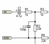
I have very limited design experience so I was looking a the P3A input circuit and wondering if adding something like it would prevent dc to enter into the amp and limit the bandwidth.
ps. please ignore r8.
Thanks
60-80W Power Amplifier
I was taking a look on the differences from F5 to F7 and seams that one of F7 designs goals was to have a limited bandwidth , so F7 ~20khz and F5 300khz.
So I was wondering if one could reduce the F5 bandwidth and make it more forgiving of source issues, high frequency noise etc .. as the F7 claims to do be.
I have very limited design experience so I was looking a the P3A input circuit and wondering if adding something like it would prevent dc to enter into the amp and limit the bandwidth.
ps. please ignore r8.
Thanks
60-80W Power Amplifier
Attachments
if adding something like it would prevent dc to enter into the amp and limit the bandwidth.
This is a typical way to limit the input bandwidth, for both DC and hf. The F7 has other differences,
though the actual schematic has not been released. The polarity of C1 may have
to be reversed. Or use a non-polarized type instead, which also has lower distortion.
Last edited:
This is a typical way to limit the input bandwidth, for both DC and hf. The F7 has other differences,
though the actual schematic has not been released. The polarity of C1 may have
to be reversed. Or use a non-polarized type instead, which also has lower distortion.
Thanks , yes C1 is recommended to be non-polarized.
Thanks , yes C1 is recommended to be non-polarized.
Usually the components are chosen for the bass rolloff pole to be around 2Hz,
and the hf rolloff pole to be around 40 or 50kHz. Then C2 would be 3.3nF,
and C1 would be 3.6uF. The hf filter as shown rolls off at around 1.6MHz.
Last edited:
Usually the components are chosen for the bass rolloff pole to be around 2Hz,
and the hf rolloff pole to be around 40 or 50kHz. Then C2 would be 3.3nF,
and C1 would be 3.6uF. The hf filter as shown rolls off at around 1.6MHz.
Interesting.
Some people don't like too many watts (they prefer 5) and some other people don't like too much bandwidth (they prefer 20 Khz) 🙂
I always recommend two passive filters at the input of audio equipment.
A high pass about a decade below the lowest signal you want to pass.
A low pass about a decade above the highest frequency you want to pass.
For a full bandwidth audio amplifier that is traditionally expected to pass 20Hz to 20kHz, one could set the passive input filtering to 2Hz to 200kHz. There is a lot of leeway to the frequencies you choose. Easily an octave either side.
The input capacitor can pass some leakage current. It is better to allow this leakage current to pass to signal return. You can do this by adding a 2M2 resistor across the input socket.
You can also add an extra pole to the low pass filtering to attenuate the extreme RF by adding a 22pF to 47pF across the input socket. This interacts with the source impedance and the interconnect inductance to create a 2pole filter, but at vhf.
Some amplifiers like the F5 use the capacitance of the input stage transistor to create the low pass filter instead of adding a filter stage. I don't like that, even though Pass seems to favour this method.
Last edited:
- Status
- Not open for further replies.
- Home
- Amplifiers
- Pass Labs
- F7 vs F5