At least one of the Pass amplifiers uses a common emitter (actually common source) output.
This is relatively uncommon, has it been analysed in this forum or is there a link to further information?
David
This is relatively uncommon, has it been analysed in this forum or is there a link to further information?
David
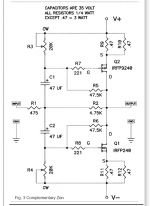
It has been used by decades. I remember automovile radios with PNP germanium (like the AD149) transistors using Class A output stage in this way.
Maybe this:
http://www.firstwatt.com/graphics/F2J%20SCH.gif
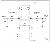
The pullup transistor "Q2" is an IRFP9240 Pchannel MOSFET operated as a constant current source (with Q3 + R16 + R17 setting the current)
The pulldown transistor "Q1" is a SemiSouth silicon carbide Nchannel MOSFET operated as a common source amplifier.
SemiSouth Labs Announces First Use of its Breakthrough Transistor in a High-Level Audio Amplifier for Consumers | Business Wire
http://www.firstwatt.com/graphics/F2J%20SCH.gif
The pullup transistor "Q2" is an IRFP9240 Pchannel MOSFET operated as a constant current source (with Q3 + R16 + R17 setting the current)
The pulldown transistor "Q1" is a SemiSouth silicon carbide Nchannel MOSFET operated as a common source amplifier.
SemiSouth Labs Announces First Use of its Breakthrough Transistor in a High-Level Audio Amplifier for Consumers | Business Wire
It has been used by decades. I remember automovile radios...
Maybe this:..
Thank you both, yes it's common in simple transistor radios and similar but up-rated circuits, I should have been more specific.
I am interested in complementary, push-pull applications - I think the F5 does this?
In particular I am interested in how the Class B cross-over transition is handled, is there an analysis similar to what B. Oliver did for emitter follower's?
Best wishes
David
Here are some more. The one named F5 (hover your mouse over the image to see the name) went into production and many were sold. Lots of people here on diyAudio built themselves an F5; search for threads.
Attachments
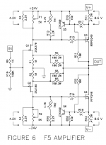
there is no class B xover transition in Papamps
Are all of his amps class A?
Audio amps are only a minor contributor to power consumption but I still want mine to be efficient, should be cooler and more reliable, quite apart from the environmental benefit.
...F5; search for threads.
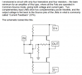
Yes, I came up with a similar circuit, then discovered the F5.
But I haven't found any analysis, I want to understand better.
Best wishes
David
But I haven't found any analysis, I want to understand better.
Hi, David!
You can start from Bart Locanthi's output triple (from latter 1960):
http://leachlegacy.ece.gatech.edu/papers/tcir/tcir.pdf
And something more modern based on it:
http://www.synaesthesia.ca/YAPOPstage.html
And then go to Middlebrook's "General Feedback Theorem".
After understanding troubles with VAS loading by output stage and thermal stabilization of 6 (or even 8 in output quad) different junctions you can search for push-pull dynamically cascoded MOSFET OPS.
The latter you best to understand OPS shoulders crossover distortion.
So, in the end you can come something near bridged OPS in truly-A.
😉
You can start from Bart Locanthi's output triple...
Hi
Thank you but the Locanthi output and other example are Emitter Follower, also called Common Collector, not Common Emitter.
Perhaps the success of the Locanthi circuit has tended to stifle other options, people just copy it, more or less.
The YAP circuit is excellent however, and I have already looked at it carefully.
I also like Middlebrook GFT and even have a thread about it in the Solid-State sub-forum, I welcome your comments.
Best wishes
David
the Locanthi output and other example are Emitter Follower, also called Common Collector, not Common Emitter.
Oh, yes, sorry for my misunderstood and ugly English!
I also like Middlebrook GFT
So, based on this approach, we can design systems without knowledge about its internal structure.
😉
May be dynamically cascoded OPS will be interest for you:

Many of Pass' ClassA amplifiers transistion into ClassB when the output current exceeds the ClassA limitation.there is no class B xover transition in Papamps
It what stops a push pull amplfier from current clipping, unlike a single ended amplifier that simply current clips when current demand exceeds the ClassA limit.
Oh, yes, sorry for my misunderstood...
No trouble, your references show excellent discernment, so I knew it was only a translation issue.
So, based on this approach...
This is a discussion that interests me very much.
We want to be able to treat subsystems as a "black 'box" and not have to know internal structure.
This simplifies the problem, I was employed as a computer System Analyst and it is the foundation of the approach.
And yet it seems that better amplifiers are possible if we know the internals.
May be dynamically cascoded OPS will be interest for you...
They are indeed of interest, the appeal is obvious and I have looked at cascodes on the OPS.
But I want efficiency and the cascodes inevitably mean less rather than more.
So I continue to be interested in Common Emitter.
Best wishes
David
This is a discussion that interests me very much.
We want to be able to treat subsystems as a "black 'box" and not have to know internal structure.
This simplifies the problem, I was employed as a computer System Analyst and it is the foundation of the approach.
Hi, David!
Please let me recommend this book to you (of course, if you doesn't have it in your collection yet):
https://www.amazon.com/gp/aw/d/0134407628/ref=dp_ob_neva_mobile
http://sv.20file.org/up1/951_0.pdf
And yet it seems that better amplifiers are possible if we know the internals.
We must clearly understand benefits and troubles of each case/approach and being informed - we must to choose less evil solution.
🙂
Do you want to DESIGN or to UNDERSTAND?
Now mostly all building blocks are good known and we just need to choose basic conception of the amp (low or deep feedback, high or low band, low or high first pole frequency, more or less noise, more or less gain, more or less power, etc) and then simply connect blocks with mostly good parameters at choosen concept.
😉
The most critical of the common emitter are the following:
1. Using supply rail as reference, so it must be fairly clear or feedback are deep enough.
2. Relatively huge parameter deviation at working period.
3. Relatively high output resistance, so deep feedback are needed again.
They are indeed of interest, the appeal is obvious and I have looked at cascodes on the OPS.
But I want efficiency and the cascodes inevitably mean less rather than more.
So I continue to be interested in Common Emitter.
First of all cascodes (with push-pull source follower) have relatively huge input resistance, this unloades VAS;
Next, as voltage at cascoded transistors are constant - influence of gate parasitic capacitance are mostly excluded, so OPS pole can be placed at higher frequency and we have easy way to tune it by gate resistors;
And the last - we have greater SOA.
Please let me recommend this book to you...
Thank you, I may have seen this when I went to the university library to skim the control theory section and find a few books for deeper study.
But I don't remember it specifically so I will look more closely.
Much of the Control Theory literature is of limited applicability to electronics, concerned with control of very unstable systems or Multiple Input Multiple Output systems that are cross coupled.
The authors I found most relevant to electronics were Isaac Horowitz and Boris Lurie, your compatriot.
I recommend their works if you have not already seen them.
The most critical of the common emitter are...
These are critical but not a problem.
For example, the open loop output impedance may be more - but there is more feedback available because the CE OPS has gain.
So the nett result is the closed loop impedance is the same, and that is all that matters.
My own compatriot Dr Edward Cherry has examined this point in detail and concludes they are equivalent in output impedance, parameter deviation sensitivity and stability but the CE has some benefits in distortion reduction of earlier sections, and implementation.
I recommend his work, very educational, especially the Journal of the AES 1982, April paper on the subject.
I want to extend his work, hence my inquiry for other references, so I do not duplicate other authors if I publish.
Cascodes have some attractions and I would like to analyse them later, if the CE work is succesful.
Best wishes
David
Last edited:
The authors I found most relevant to electronics were Isaac Horowitz and Boris Lurie, your compatriot.
Good to know! Useful books.
But, one critical aspect are commonly hidden: algorithm or procedure for designing device with maximized feedback depth.
From where to start, what steps and how long they must be, what direction to go.
🙂
Commonly known (from Niquist and Bode), the more feedback depth we wish - the more bandwidth we need.
Thinking deeper we are founding two-three-four-more pole compensation schemes.
Based on long lasting listening of wide variety of audiodevices i can pick out two truly different approaches:
1. Design lower feedback (even without Miller cap) with intrinsic linear stages(may be with intrinsic instage 100% feedback)
2. Design huge feedback with intrinsic nonlinear/lesslinear stages
And a lot of thoughts in between of them.
My own compatriot Dr Edward Cherry has examined this point
I want to extend his work, hence my inquiry for other references, so I do not duplicate other authors if I publish.
Cascodes I may consider later, if the CE work is succesful.
David, i have no doubt, community will look forward for your ideas and results.
Especially if straight converting from PCM to PWM with fast enough feedback to digital domain will be effortless to win battle for our hearts and purses with linear devices.
😉
But, one critical aspect are commonly hidden: maximized feedback depth.
From where to start, what steps...
This has occupied my attention for several years.
I was surprised that I could not find some analysis that proves how to maximize this.
I studied mathematics and this looks like a classic problem for optimization.
Finally I have some results on how to do this, that is part of the reason that I asked about Common Emitter Output.
Typical Emitter Follower basically has inbuilt -ve feedback, no flexibility to alter for optimization.
CE allows more freedom.
Commonly known (from Niquist and Bode), the more feedback depth we wish - the more bandwidth we need.
Yes, no way around this
... two-three-four-more pole compensation schemes.
Two pole + zero is effective but safe. This is what I use.
More poles and zeros has theoretical benefit but practical problems when the amp clips and the linearity assumptions become invalid.
... two truly different approaches:
As you say, many of the more linear devices simply have internal -ve feedback.
There is more freedom if the feedback is external, then we can control it exactly, not just accept the default internal value.
This is my point with CE versus EF.
from PCM to PWM with fast...
First I want to work out linear amplifiers😉
Best wishes
David
Guru Dave, it sounds like you're already convinced (as am i)
If the lack of a deterministic formulation of the Barney optimal bias point is the remaining holdback, then I have a solution:
Use mosfets instead 😀
If the lack of a deterministic formulation of the Barney optimal bias point is the remaining holdback, then I have a solution:
Use mosfets instead 😀
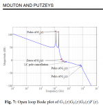
Bruno Putzeys and the Class D gang are actively pursuing the "more loop gain and more feedback" approach. Their AESDenmark paper describes an amplifier with five poles and four zeroes, achieving huge amounts of loop gain at 10 kilohertz. Here is one of their figures.
_
_
Attachments
This has occupied my attention for several years.
I was surprised that I could not find some analysis that proves how to maximize this.
I studied mathematics and this looks like a classic problem for optimization.
Finally I have some results on how to do this, that is part of the reason that I asked about Common Emitter Output.
Typical Emitter Follower basically has inbuilt -ve feedback, no flexibility to alter for optimization.
CE allows more freedom.
David, we are clearly at the point!
Let me think about this?
My thoughts are next:
1. We must start from the OPS pole.
At a given frequency we can simply estimate how deep feedback we can achieve with 1-2-3-more pole correction.
2. Next we must choose place for first pole, i can suggest, that we want to have constant feedback depth (and may be phase) all around audioband.
3. Next with your choise of 2p+1z we just need to make mathematical criteria, which would allow to maximize band with -40 dB/decade slope. This provide mathematically optimized frequency point to place our zero.
Lets assume safe gain margin at +-10 dB and phase margin at no less than 30 degree. Just write and solve the equation.
😉
4. In the case of 3p+2z (or 4p+2z) we need to maximize band with -60 dB/decade with ability to restore phase to safe 30 degree margin. So equation can be solved again.
Yes, no way around this
No, we can design stable systems under Niquist criteria.
The criteria is how precise we can estimate and calculate parts tolerances and how we insane in estimating PCB/devices parasitic parameters.
All, that we need - is to exclude instability point [0dB, -180degree] or [-1, 0]
Two pole + zero is effective but safe. This is what I use.
More poles and zeros has theoretical benefit but practical problems when the amp clips and the linearity assumptions become invalid.
2p+1z is a fairly like a Miller correction.
Let's go two another ways.
1. You can place 1p at a frequency, which allow 2p of the OPS to be at -10 dB gain frequency point. So no Miller capacitor with fairly high-frequency OPS.
😉
2. You can design stable system with 4p+2z. Just place level detection at the input and load protection at the output. Last p- must be at -10 dB gain frequency.

But, of course, square wave will be with over- and under-shoots.
First I want to work out linear amplifiers😉
There are some questions, please, spent your time to our proper understanding of design goals:
1. What amout of feedback depth at 20 kHz you want to achieve?
2. What Ft can you provide?
3. What PSRR of your supply are?
4. What input noise/resistance can you provide?
5. What closed-loop gain do you want?
6. What THD do your naked OPS have?
And then we can discuss much more clearly.
I can show you 100, 120 and even 150 dB depth at 20 kHz, but do you really need so much?
Guru Dave, it sounds like you're already convinced (as am i)
If the lack of a deterministic formulation of the Barney optimal bias point is the remaining holdback, then I have a solution:
Use mosfets instead 😀
Not only, just add bias them to glorious A.
😀
amplifier achieving huge amounts of loop gain at 10 kilohertz. Here is one of their figures.
Please, let me know since when something like 60 dB starts to be "huge amounts"?
😉
He can use something like $100 LTC2208/2209 160 MHz ADC for closing digital loop. I'm not saying about modern JESD204b ADC's.
And, of course, previous generation middle lineup Xilinx like this:
https://www.ebay.com/itm/361449531930
Last edited:
David, we are clearly at the point!
Let me think about this...
Here is a link that shows what I believe is reasonable with an Eimtter Follower OPS
>My EF Amplifier Simulation<
I am happy with that result but perhaps a CE OPS can do better.
So you can think about that, while I think of a detailed reply to your post😉
Best wishes
David
Last edited:
- Status
- Not open for further replies.
- Home
- Amplifiers
- Pass Labs
- Common Emitter OPS?