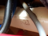
Hi, I Bought a complete set of dali speakers that included a set of 7s that i have been after for a long time, one speaker works great but the other the dome tweeter not working i tested it and its fried, i swapped a tweeter from a dali 6 and still did not work, so i removed the crossover and and what a mess, looks to me like the resistor has got very hot and cracked and the cap has leaked, Need help with identifying the resistor as the first part of the text has faded with the heat.
I will be replacing all caps and the mystery Resistor? ??W8R2J
I will be replacing all caps and the mystery Resistor? ??W8R2J
Attachments
Last edited:
I may be stating the obvious but it wasn't apparent in your post. Did you reference the other crossover to see if the text was still legible?
Sorry i should of mentioned that yes i pulled the other crossover out and same resistor is cracked due to over heating i guess.I may be stating the obvious but it wasn't apparent in your post. Did you reference the other crossover to see if the text was still legible?
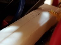
thanks for that i have just ordered some new resistors. 10W8R2JThe top layer has one with similar size. It's a 8.2 ohm 10W resistor.
cheers
Maybe obvious, but when you replace them keep some air space around them and don't have them touching anything that burns.
thanks for that i have just ordered some new resistors. 10W8R2J
cheers
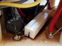
I'd advise you to check the capacitance of the 33uf bi-polar lytic next to the faulty resistor. It may be affected by the resistor.
I have order all new mundorf Mcap 250, what would cause that resistor to crack like that.Maybe obvious, but when you replace them keep some air space around them and don't have them touching anything that burns.
Yeh, replacing all the caps with mundorf Mcap 250, except for the small .68 cap that will be a different band. cheersI'd advise you to check the capacitance of the 33uf bi-polar lytic next to the faulty resistor. It may be affected by the resistor.
what would cause that resistor to crack like that.
If I read that correctly as a question, continuous high power operation combined with pi$$poor thermal dissipation design would be my first guess. What appears to be melted insulation on wire carelessly dressed over the ceramic body, and charring of the board underneath is a pretty big clue.
Simply shoehorning replacements for damaged parts into the same space will likely only delay an inevitable failure there or elsewhere in the assembly.
The circuit topology may be completely acceptable, but the construction is very poorly thought out.
Thanks for your feedback, should i upgrade all the resistors as well and what type and brand should i get.If I read that correctly as a question, continuous high power operation combined with pi$$poor thermal dissipation design would be my first guess. What appears to be melted insulation on wire carelessly dressed over the ceramic body, and charring of the board underneath is a pretty big clue.
Simply shoehorning replacements for damaged parts into the same space will likely only delay an inevitable failure there or elsewhere in the assembly.
The circuit topology may be completely acceptable, but the construction is very poorly thought out.
I don't use ceramic wirewound in speaker. I'd recommend Caddock MP920/930 thick film resistor. Expensive, but it sounds good. You need heat sink to use them.
Thanks for all the info, i really only want to do this once but i can now see that this could get quite addictive, modding speakers.I don't use ceramic wirewound in speaker. I'd recommend Caddock MP920/930 thick film resistor. Expensive, but it sounds good. You need heat sink to use them.
No reason to spend a lot just go from 10w to 15w resistors (check size or just put some space between it and board-1/16-1/8") and you'll be fine. I like Mills.
Sent from my iPhone using Tapatalk
Sent from my iPhone using Tapatalk
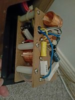
It's not about upgrading parts quality or even power rating - the physical layout still needs reasonable amount of space for thermal dissipation, and larger wattage rating parts will be even more cramped. This one is quite simply not well thought out from that point of view. You may need to reconstruct the XO by further spacing the sandwiched boards, and certainly redressing wires to not lay in direct contact with power resistors.
Also note that BPE caps were usually implemented for both cost and space saving reasons. While I've yet to hear an XO not improved by changing out old BPEs with film types, the latter are generally much larger, which only compound the problem of trying to stuff than many components in a confined space. If these are the enclosures, there's more than enough space to rebuild and still give all the parts more breathing room . Of course outboarding the XO would be even better 😉
Also note that BPE caps were usually implemented for both cost and space saving reasons. While I've yet to hear an XO not improved by changing out old BPEs with film types, the latter are generally much larger, which only compound the problem of trying to stuff than many components in a confined space. If these are the enclosures, there's more than enough space to rebuild and still give all the parts more breathing room . Of course outboarding the XO would be even better 😉
An externally hosted image should be here but it was not working when we last tested it.
yes i just looked them up, i can only find 8ohm ones will that be ok and i just went through my old computer parts and found some old heat sinks. i was thinking i will just do the two on the bottom layer with the thick film, and use the Mundorf MResist MOX 10W 2% Resistors for the top layer.? Also i don't drive my speakers to there limit. -10db is my max ever, will be using a Sherwood Newcastle A965 to drive the fronts only.I don't use ceramic wirewound in speaker. I'd recommend Caddock MP920/930 thick film resistor. Expensive, but it sounds good. You need heat sink to use them.
I do have some heat sinks with heat pipes that may me the go.
I will look at the layout when i get all my parts, having the resistor under the cap cant be great so i will try and change that around so the heat can rise without heating other parts, there is more room if parts are pushed to the outside of the board.
I will look at the layout when i get all my parts, having the resistor under the cap cant be great so i will try and change that around so the heat can rise without heating other parts, there is more room if parts are pushed to the outside of the board.
Too late for that, everyone has a different idea i guess, i now have lots of parts ordered i guess they will come in handy for other speakers.No reason to spend a lot just go from 10w to 15w resistors (check size or just put some space between it and board-1/16-1/8") and you'll be fine. I like Mills.
Sent from my iPhone using Tapatalk
Last edited:
- Status
- Not open for further replies.
- Home
- Loudspeakers
- Multi-Way
- Dali Ikon 7 crossover repair help needed