I have buckets of IRFP240 as well but was saving them for cap multipliers, but this is certainly a worthwhile endeavor. Order some more to replenish bucket 🙂
A good Rds on for a SS relay is <10mohmsbuckets of IRFP240
Two are in series adding <20mohms to the output impedance.
Rds on of a 240 is 180mohms and the 9240 is 500mohms.
You need a big bucket !
A splendid idea, I really like it.
At the same time, I can't help wondering what the subjectivist audiophile crowd will make of a great big MOSFET sitting right there in the signal path, hehehehe.
At the same time, I can't help wondering what the subjectivist audiophile crowd will make of a great big MOSFET sitting right there in the signal path, hehehehe.
A good Rds on for a SS relay is <10mohms
Two are in series adding <20mohms to the output impedance.
Rds on of a 240 is 180mohms and the 9240 is 500mohms.
You need a big bucket !
A theoretically good value of Rds is around <10 mohm or less but this is audiophile territory... and you sometimes have to think outside the box. A slightly higher Rds can begin to take the place of a series output resistor and all the (ho-hum 😉) advantages that can go with that such as a little more isolation of the load and speaker wiring from the amplifier NFB take off point. Use of slightly differing Rds values between devices in a relay pair could offer the intriguing prospect of deliberately adding a slight non-linearity and increasing (or audibly off setting) any odd harmonic distortion generated by the amplifier itself.
A splendid idea, I really like it.
At the same time, I can't help wondering what the subjectivist audiophile crowd will make of a great big MOSFET sitting right there in the signal path, hehehehe.
And I wonder why the 'audiophile' crowd still use mechanical switches and relays. I've yet to see a small signal switch last for many years (and decades) without deterioration. They are always trouble waiting to happen.
Well, none is intended and if you detected one, it has to be a mistake (not yours, mine!)Am I seeing a copy protection in Elvee's circuit? ;-)
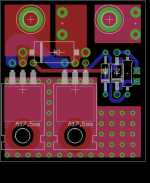
Allright, final version.
To be noted: the mosfet must be isolated from the pad (or at least one has to be), not to short the drains together.
There is now room for a TVS. Since nobody jumped in to point an error in post 17, pick your mosfets/tvs according to that.
Eagle brd attached (remove the .txt). Not tested at this point, that's what I'll send to the fab soon.
Attachments
Guy's plse help me understand. Why do you need a fet which is rated double the rail voltage ? If I use +-70V dc rails, how can the output to the speaker get to 140V dc ? If it sticks to a rail, that is only 70V. 😕
Over design. If you don't use the tvs, any mosfet rated 20% above your rail voltage will be enough.
If you use the tvs to protect the mosfets from inductive kickback, you've got to pick a mosfet with a voltage rating above the clamping voltage of the tvs. And you need a tvs with a working voltage above your rail voltage. That adds some overhead.
With 70v rails, you'd want a 82V nominal tvs. Working voltage is just 70V so leakage would be low even with a fault. But the clamping voltage is 113v. So to be safe, you'd need a 120v mosfet at least.
Guy's plse help me understand. Why do you need a fet which is rated double the rail voltage ? If I use +-70V dc rails, how can the output to the speaker get to 140V dc ? If it sticks to a rail, that is only 70V. 😕
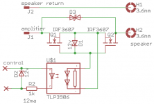
If we look at the schematic in post #27, ignoring D3, when node J1 is sticking to the positive rail causing a large current going from J1-Q1-Q2-H2-Speaker-H1-J2 at the moment Q1 and Q2 are turned off, the back EMF of the speaker system can send H2 towards negative potentials far beyond that of the negative rail. Because of that I would diode-clamp H2 to both positive and negative rails with two diodes. And that is also why the MOSFETs need to have a breakdown voltage greater than 2x rail voltage.
I would not put in a D3 the way the schematic shows, as it defeats what the MOSFETs are there to do: to detach, not attach, the speaker from the rails, or any other part of the amp, when things come up.
I use 150V, 5 mOhm IPT059N15N3 in a few amp builds and they are good. Quite expensive though.
A diode to the rails is a good solution. But it requires to run the rails to the board.
D3 being of a higher working voltage than the max voltage output of the amp can hardly be said to attach the speaker to the amp's output.
This being said, I cannot see why one couldn't simply wire the tvs from H1 to H2 (output to gnd). That would dump any spike into the gnd rather than the rails.
D3 being of a higher working voltage than the max voltage output of the amp can hardly be said to attach the speaker to the amp's output.
This being said, I cannot see why one couldn't simply wire the tvs from H1 to H2 (output to gnd). That would dump any spike into the gnd rather than the rails.
The TVS across the relay mosfets is to protect just the mosfets, as the other end of the speakers are connected to GND then the normal operating maximum voltage across the mosfets is +PWR or -PWR to GND, not the double voltage by +PWR to -PWR.... The TVS take care of any not normal pulses....
So an amplifier powered by t.ex. max +-60V can do with TVS with 60V minimum breakdown, like a SMCJ54CA and 80V mosfets. Higher spec'ed mosfets are just overkill....
The amplifier itself is supposed to already be protected by diodes, if mosfet output devices then the mosfet diodes, if bipolar output devices then there should be diodes across the output transistors.
I'm not aware of any research into it, but I believe it's limited how powerful back pulse there can come from the speakers, bipolar amplifiers often have the transistors protected by regular 1A diodes....
....
So an amplifier powered by t.ex. max +-60V can do with TVS with 60V minimum breakdown, like a SMCJ54CA and 80V mosfets. Higher spec'ed mosfets are just overkill....
...not so when the load is inductive, as are most speaker systems...thinking about how sparks are generated with an ignition coil in a gasoline engine....
The TVS across the relay mosfets is to protect just the mosfets, as the other end of the speakers are connected to GND then the normal operating maximum voltage across the mosfets is +PWR or -PWR to GND, not the double voltage by +PWR to -PWR.... The TVS take care of any not normal pulses....
the "not normal pulses" are coming from the speaker as an electric current going through it gets interrupted, as the stored energy, in forms of both magnetic field in the inductive components and the back air pressure in the speaker cabinet is being released into the parasitic capacitance. Therefore, a TVS immediately across the speaker terminals, as suggested by "00940" in post #31, makes most sense, as it free-wheels the stored energy and damps it out locally, instead of sending it across the MOSFETs, further into the amp.
Last edited:
pulldown connections.Well, none is intended and if you detected one, it has to be a mistake (not yours, mine!)
Sorry, I must be thick, but I don't see....pulldown connections.
One tends to be blind to his own mistakes, even if they are glaringly obvious to anyone else eyes
Soooo...
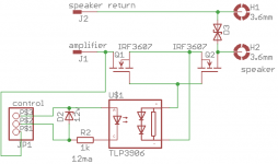
Can this schematic be considered final ? I removed the unnecessary protection zener (the tlp3906 cannot generate enough voltage), added a connector with a pin for the +12v control line, gnd and sensing of the amplifier output and moved the tvs across the output's posts.
Can this schematic be considered final ? I removed the unnecessary protection zener (the tlp3906 cannot generate enough voltage), added a connector with a pin for the +12v control line, gnd and sensing of the amplifier output and moved the tvs across the output's posts.
Attachments
One tends to be blind to his own mistakes, even if they are glaringly obvious to anyone else eyes
Flip flop 'CLK' pin is missing a pull-down, the 'CLR' pin has two.
Well spotted! I could have spent a thousand years without seeing itFlip flop 'CLK' pin is missing a pull-down, the 'CLR' pin has two.
- Status
- Not open for further replies.
- Home
- Amplifiers
- Solid State
- Mosfet-based replacement for loudspeakers relays