Yesterday, I was playing with different ways of wiring the input ground wires in my preamp. The sound difference was quite large.
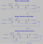
The diagram below shows the way I wired the input of the preamp. Wiring 1 sounds very boring. Wiring 3 sounds far more detailed and is a lot more musical.
The diagram below shows the way I wired the input of the preamp. Wiring 1 sounds very boring. Wiring 3 sounds far more detailed and is a lot more musical.
Attachments
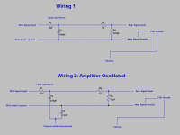
So today, I wanted to wire my power amp in the same way as wiring 3 in the previous post.
I changed from wiring 1 to wiring 2 in the diagram below.
The power amplifier oscillated! Huge waves shown in my scope. The heatsinks were very hot for both channels. One of the Zobel resistor smoked.
I then removed the 2.2nF. When I also disconnected the 470pF, the oscillation was gone. As soon as I connected the 470pF without the 2.2nF, the oscillation occurred again. So it was the 470pF causing the problem.
Why? Thanks for your help in advance.
Attachments
Last edited:
Yesterday, I was playing with different ways of wiring the input ground wires in my preamp. The sound difference was quite large.
The diagram below shows the way I wired the input of the preamp. Wiring 1 sounds very boring. Wiring 3 sounds far more detailed and is a lot more musical.
Try # 1 but now with the chassis ground point at the input. That should be the best one.
Jan
So today, I wanted to wire my power amp in the same way as wiring 3 in the previous post.
I changed from wiring 1 to wiring 2 in the diagram below.
The power amplifier oscillated! Huge waves shown in my scope. The heatsinks were very hot for both channels. One of the Zobel resistor smoked.
I then removed the 2.2nF. When I also disconnected the 470pF, the oscillation was gone. As soon as I connected the 470pF without the 2.2nF, the oscillation occurred again. So it was the 470pF causing the problem.
Why? Thanks for your help in advance.
The 470pF is not the problem; the problem is once you put in the 470pF you created a ground loop, which should be clear from diagram # 2.
Again, the best is to ground the chassis at only one point, preferably at the input.
Jan
Thanks, Jan.
Why didn't it have a problem with the preamp? The power amp with the same wiring occillated without load and without input signal!
I will definitely try your suggestion. Does it apply to both the pre and power amps?
Why didn't it have a problem with the preamp? The power amp with the same wiring occillated without load and without input signal!
I will definitely try your suggestion. Does it apply to both the pre and power amps?
Try # 1 but now with the chassis ground point at the input. That should be the best one.
Jan
the signal wiring connection must be TWO WIRE and the LOOP AREA in the connection must be minimised.The 470pF is not the problem; the problem is once you put in the 470pF you created a ground loop, which should be clear from diagram # 2.
Again, the best is to ground the chassis at only one point, preferably at the input.
Jan
layout 2 and 3 of post 1 breaks this rule.
Only layout 1 can be correct.
You are probably hearing interference being added to your signal and perceiving that as increased detail.
The Power Amp is receiving that increased interference and when you rewire it to increase the loop areas it tells you, you have made it wrong by oscillating due to excess HF interference.
MINIMISE LOOP AREA !
The power amp works with MUCH higher currents, think 10A class instead of 1 mA or 0.01mA if we are talking only input signal currents.
Now a piece of chassis or piece of wire measuring, say, 0.05 ohms (**everything** has some resistance, even if thumb thick copper wire, and any conductor of any length has some inductance) and will appear as a perfect ground at microscopic currents but not when full amperes are going through it, so developing important and very measurable voltage drops.
If you trust a "ground" which really is showing quite a few mV sample of output signal, you may have a big problem in yur hands, shown as distortion, instabillity or full oscillation.
Good grounding practice tries to minimize that, mainly by keeping "dirty" (speaker return and main filters charging current ripple) and "clean" grounds separate.
FWIW hybrid designs try to keep Digital (very dirty) and Audio grounds separate.
About what you heard, if your premp were properly grounded you should hear no difference.
Going from "dull" to "detailed and musical" *could* mean you now have some marginal instability which introduced a high frequency peak which seems to give it more definition, because all that can be expected from different grounding schemes is a reduction in hum/buzz or interference, or even improved crosstlk performance, but not an *equalization* change.
the signal wiring connection must be TWO WIRE and the LOOP AREA in the connection must be minimised.
layout 2 and 3 of post 1 breaks this rule.
Only layout 1 can be correct.
You are probably hearing interference being added to your signal and perceiving that as increased detail.
The Power Amp is receiving that increased interference and when you rewire it to increase the loop areas it tells you, you have made it wrong by oscillating due to excess HF interference.
MINIMISE LOOP AREA !
Andrew,
Layout 3 is TWO WIRE at LF. The extra loop introduced is at RF only. I thought it was to divert RF away from the signal and signal ground, but of course, I made a mess of it.
I thought you mentioned previously that capacitors are used to shunt RF from RCA input wires and RCA input ground as well as speaker returns to chassis.
It is in fact that I remembered you said that so I tried it. Perhaps I misunderstood you?
Regards,
Bill
Last edited:
Going from "dull" to "detailed and musical" *could* mean you now have some marginal instability which introduced a high frequency peak which seems to give it more definition, because all that can be expected from different grounding schemes is a reduction in hum/buzz or interference, or even improved crosstlk performance, but not an *equalization* change.
Thanks.
I thought of the same thing. But the "detailed and musical" sound was also "quieter" with a blacker background, far better dynamic, more 3D sound, etc. I use only classical and jazz music to test sound and I am fairly familiar with live sound as I go to live classical concerts regularly.
I use only classical and jazz music to test sound and I am fairly familiar with live sound as I go to live classical concerts regularly.
Your results mirror my own rather closely - what's happening in the #1 layout for your preamp is that high frequency common-mode noise currents are getting superimposed on the audio signal. In the second and third one, they're being shunted to ground in differing degrees and hence appear to a lesser extent imposed on the audio.
Incidentally I've come to the same conclusion as Jan - the optimum place for the 0V to chassis connection is right at the input sockets.
If the optimum place for the 0V to chassis connection is right at the input socket(s), then how do you do it in a preamp when there are multiple RCA inputs? Do you do it after the input rotary selector?
I think yes, that would be my approach - switch both the 'hot' and '0V' side of all the inputs so that there are no extra ground loops with all those sources connected. But then the construction should be class II (double insulated) because you'll have exposed metal parts which aren't bonded to chassis.
The vast majority of hi-fi equipment manufacturers agree - even if just because it makes units with a lot of inputs and outputs a lot easier to build.Incidentally I've come to the same conclusion as Jan - the optimum place for the 0V to chassis connection is right at the input sockets.
Nope, all the RCAs are screwed to the backplate. Nice, low-impedance connection. Pick one spot on there for your star ground.If the optimum place for the 0V to chassis connection is right at the input socket(s), then how do you do it in a preamp when there are multiple RCA inputs? Do you do it after the input rotary selector?
What I am not sure of is why so many mfrs seem to have issues with their HDMI. It is as if they may be connecting cable shield to local ground rather than straight to chassis.
If the 470pF creates multiple RF current paths because of multiple connection points to the chassis, then I am now worried.
The large 625VA transformer is bolted on the chassis, and there can be hundreds of pF capacitance from the transformer to the chassis. I have also had the large computer grade screw terminal reservoir capacitors directly placed on top of the chassis (caps on bottom screws on top) and capacitor cans (positive and negative rail connections) can form some capacitance to the chassis. I would have multiple "chassis" connection points for the power supply alone.
Do you think that is a problem? Do I need to have some insulator / non-conductive / plastic layer to lift up the transformer and the reservoir caps from the chassis?
Nope, all the RCAs are screwed to the backplate. Nice, low-impedance connection. Pick one spot on there for your star ground.
I wonder why all RCA sockets are insulated from the chassis.
Do you mean to find non-insulated RCA sockets? or alternatively, take out the insulator from the RCA sockets and screw them to the backplate, i.e. the shield is connected to the backplate?
I think yes, that would be my approach - switch both the 'hot' and '0V' side of all the inputs so that there are no extra ground loops with all those sources connected. But then the construction should be class II (double insulated) because you'll have exposed metal parts which aren't bonded to chassis.
That was what I thought so I bought an expensive input selector that includes switching the ground wire.s I have not used it yet.
But then I have another worry. The contact resistance of the signal wire does not cause distortion but the contact resistance of the ground wire does. No matter how high the quality of the selector, the contact resistance is still there, possibly much higher than the contact resistance of the RCA due to small contact area.
So I was thinking about soldering all the input ground wires together and not worry about switching the input ground wire.
I am undecided.
Because that's how stuff often used to be built back in the olden days. Grundig did this way into the late '80s. I don't think any mass market equipment has for 20+ years. Building a home theater receiver like that would be a nightmare.I wonder why all RCA sockets are insulated from the chassis.
Hell no, unless you plan on redoing the entire grounding arrangement. Which in turn is way more effort than it's worth, given that things seem to be working OK stock (unlike that Sansui AU-5900 thread recently).Do you mean to find non-insulated RCA sockets? or alternatively, take out the insulator from the RCA sockets and screw them to the backplate, i.e. the shield is connected to the backplate?
Incidentally I've come to the same conclusion as Jan - the optimum place for the 0V to chassis connection is right at the input sockets.
Do you connect your RCA socket to the chassis at the location just next / closest to the RCA socket or via a wire going to somewhere else.?
If the 470pF creates multiple RF current paths because of multiple connection points to the chassis, then I am now worried.
The large 625VA transformer is bolted on the chassis, and there can be hundreds of pF capacitance from the transformer to the chassis. I have also had the large computer grade screw terminal reservoir capacitors directly placed on top of the chassis (caps on bottom screws on top) and capacitor cans (positive and negative rail connections) can form some capacitance to the chassis. I would have multiple "chassis" connection points for the power supply alone.
Do you think that is a problem? Do I need to have some insulator / non-conductive / plastic layer to lift up the transformer and the reservoir caps from the chassis?
It should be no problem when the ground to the chassis and the source is connected in one place only as discussed. There may be some parasitic current through the transformer windings to protective earth, but since the voltage that could result from it cannot get in series with the signal, it's immaterial. Said in another way, you may have say a few mV junk between the input ground chassis point and the point where the xformer bolt sits, but that's outside of the signal circuit.
Jan
Do you connect your RCA socket to the chassis at the location just next / closest to the RCA socket or via a wire going to somewhere else.?
I arrange to have the chassis ground bolt as close as practicable to the input sockets and wire their 0V sides to a tag on that bolt with as short wires as I can manage.
- Status
- Not open for further replies.
- Home
- Amplifiers
- Solid State
- Wiring the input ground in various ways. Here are the results.