hello,
I've started building this high gain pre amp circuit to have a muck around with, im wondering what size pots i can get away with with it only being a pre amp?
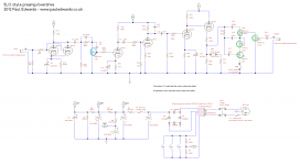
i have a large pot from a tube radio for the first vr circled in blue because i guess its going to see high voltage?
im not sure if i can get away with using the smaller pots that are normaly used in solid state equiptment for the final section vr's that are circled in green because they run from the cathode?
thanks
I've started building this high gain pre amp circuit to have a muck around with, im wondering what size pots i can get away with with it only being a pre amp?
i have a large pot from a tube radio for the first vr circled in blue because i guess its going to see high voltage?
im not sure if i can get away with using the smaller pots that are normaly used in solid state equiptment for the final section vr's that are circled in green because they run from the cathode?
thanks
Attachments
im not sure if i can get away with using the smaller pots that are normaly used in solid state
equiptment for the final section vr's that are circled in green because they run from the cathode?
The circuit needs large ohm values for the pots, but the physical size doesn't matter.
Capacitors block the high DC voltage in tube circuits, as well as in ss circuits.
A volume control with DC on it would fail right away.
There is no high voltage on your volume control.
The high volts from first stage is blocked with a coupling capacitor.
The next grid is at zero volts anyway DC wise.
A small wattage one would work fine.
The high volts from first stage is blocked with a coupling capacitor.
The next grid is at zero volts anyway DC wise.
A small wattage one would work fine.
sorry i ment to write power rating for the vr's not the ohm value (i have limited parts) thanksThe circuit needs large ohm values for the pots, but the physical size doesn't matter.
Capacitors block the high DC voltage in tube circuits, as well as in ss circuits.
A volume control with DC on it would fail right away.
sorry i ment to write power rating for the vr's not the ohm value (i have limited parts) thanks
Same thing, the power is very low due to the high impedance. Any power rating will do.
i had another couple of questions if you have time to answer,
my pt is 165v-0-165v center tap, the schematic shows a pt with no center tap. should i ground the center tap on my pt or leave it disconnected and isolate it to follow the schematic?
also the only caps i have for my ps are lower power rated than in the schem.
i have 450v 100uf and 400v 47uf's, do you think these are still with in the range and wont blow?
thanks
my pt is 165v-0-165v center tap, the schematic shows a pt with no center tap. should i ground the center tap
on my pt or leave it disconnected and isolate it to follow the schematic? i have 450v 100uf and 400v 47uf's,
do you think these are still with in the range and wont blow?
The schematic's 320VAC winding into a FWB rectifier gives around 450VDC at the first capacitor.
Your 165V-0-165V could be used in a similar way, just not using the center tap.
Be sure to tape it off and isolate it well.
It's important to rate capacitors conservatively in DC voltage. Normally you would use at least a 500V cap
for the first one, with the highest voltage (if the actual voltage is 450V), preferably more.
You could use two 400V caps in series (with shunt 200k resistors on each to divide the voltage predictably).
The other caps in the power supply probably can be 450V ratings.
Last edited:
thanks for replying I will order some more parts.The schematic's 320VAC winding into a FWB rectifier gives around 450VDC at the first capacitor.
Your 165V-0-165V could be used in a similar way, just not using the center tap.
Be sure to tape it off and isolate it well.
It's important to rate capacitors conservatively in DC voltage. Normally you would use at least a 500V cap
for the first one, with the highest voltage (if the actual voltage is 450V), preferably more.
You could use two 400V caps in series (with shunt 200k resistors on each to divide the voltage predictably).
The other caps in the power supply probably can be 450V ratings.
also I have some of these DIODE BRIDGE RECTIFIER KBPC5010 50A 1000V F H1E1
is it possible to use as a substitute for the uf5408 rectifier and also use it other amp builds? thanks
Last edited:
> DIODE BRIDGE RECTIFIER KBPC5010 50A 1000V
That looks about 1,000 times more Silicon than you need. And over 10X the cost.
Like: I need a dog-porch. I figure 2x3 sticks are strong enough. I look around and find only 10"x16" timbers (lot of big trees here). Will that work? Sure! And the dog weight will never strain it.
And a "too big" rectifier in the hand beats shipping-fees for a "right size" rect.
is it possible to use as a substitute for the uf5408 rectifier
and also use it other amp builds?
It may be ok, but the 1kV voltage rating seems somewhat marginal for both of the diodes,
in an amp with a 450VDC supply.
cheers i bought them about 5 years ago when i knew next to nothing about power ratings. i was worried if didnt use ultra fast diodes for this project i might get a higher voltage drop> DIODE BRIDGE RECTIFIER KBPC5010 50A 1000V
That looks about 1,000 times more Silicon than you need. And over 10X the cost.
Like: I need a dog-porch. I figure 2x3 sticks are strong enough. I look around and find only 10"x16" timbers (lot of big trees here). Will that work? Sure! And the dog weight will never strain it.
And a "too big" rectifier in the hand beats shipping-fees for a "right size" rect.
Funny you should say that
I'd built an amp with 450 B+ and while quickly turning it off and on, while connected to a Variac, blew the fuse. It took me a little too long to determine one of the 54xx 1kv rectifier diodes had shorted to 200 ohms. It was puzzling until recently I read up on diode voltage ratings vs. secondary transient voltage levels.
A 325 volts secondary peaks much higher than that, (and I believe the Variac's inductive reactance only added to the problem). Is that correct? I guess that's why I see those 54xx series diodes stacked on some amp builds.
colorcat.
It may be ok, but the 1kV voltage rating seems somewhat marginal for both of the diodes,
in an amp with a 450VDC supply.
I'd built an amp with 450 B+ and while quickly turning it off and on, while connected to a Variac, blew the fuse. It took me a little too long to determine one of the 54xx 1kv rectifier diodes had shorted to 200 ohms. It was puzzling until recently I read up on diode voltage ratings vs. secondary transient voltage levels.
A 325 volts secondary peaks much higher than that, (and I believe the Variac's inductive reactance only added to the problem). Is that correct? I guess that's why I see those 54xx series diodes stacked on some amp builds.
colorcat.
I guess that's why I see those 54xx series diodes stacked on some amp builds.
Sometimes parallel, high value resistors are added to each series diode in a stack,
to ensure equal voltage division and maximize their voltage blocking ability.
- Status
- Not open for further replies.
- Home
- Live Sound
- Instruments and Amps
- basic potentiometer help please