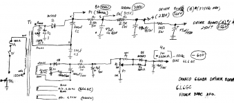
The problem with Sovtek 5AR4s lies in the area of voltage handling. The SS diode tweak shores the weak spot up. The Sovtek variant has no problem in delivering the rated 250 mA. The graphic shows 1N4007s, but I suggest UF4007s. The idea is that less switching noise, from the outset, is better, even though the vacuum rectifier blocks said noise.
SS rectified B+ in a Dyna ST70 is certainly possible and I have a somewhat involved scheme for that. What must be dealt with is the "taller" B+ rail voltage, which can damage filter caps. of the OEM WVDC, among other unpleasant items. Retaining vacuum rectification, installing a decent choke, and increasing the value of the B+ reservoir cap. may be an easier path.
In any event install caps. at the I/Ps to create high pass poles that corner at about 19 Hz. Protect the O/P "iron" cores against saturation by the LF error correction signal trying to linearize infrasonic noise.
Attachments
The problem with Sovtek 5AR4s lies in the area of voltage handling. The SS diode tweak shores the weak spot up. The Sovtek variant has no problem in delivering the rated 250 mA. The graphic shows 1N4007s, but I suggest UF4007s. The idea is that less switching noise, from the outset, is better, even though the vacuum rectifier blocks said noise.
SS rectified B+ in a Dyna ST70 is certainly possible and I have a somewhat involved scheme for that. What must be dealt with is the "taller" B+ rail voltage, which can damage filter caps. of the OEM WVDC, among other unpleasant items. Retaining vacuum rectification, installing a decent choke, and increasing the value of the B+ reservoir cap. may be an easier path.
In any event install caps. at the I/Ps to create high pass poles that corner at about 19 Hz. Protect the O/P "iron" cores against saturation by the LF error correction signal trying to linearize infrasonic noise.
It's easy enough to throw away some B+ voltage with a power resistor, so you can get rid of the 5AR4 filament load on the too hot power transformer, but watch out for what B+ goes up to, when first turned on, before the tubes warm up and start to conduct, thereby loading down the transformer, and lowering B+ significantly. Any filter caps need to be able to handle that peak voltage.
Bob,
My scheme for a SS rectified ST70 turns those additional B+ volts into an asset. Switch to combination bias, by "standing" each O/P tube pair on a 100 Ω/470 μF. network. A convenient "idle" current test point is present and having only 1 bias set trim pot. in each channel is no longer problematic.
Keep the power trafo cool by using the minimum amount of capacitance in the 1st filter position that's sufficient to keep the B+ rail voltage up. A decent choke and lots of capacitance in the reservoir position deal with ripple. A CL-130 inrush current limiting thermistor between the rectifying diodes and the B+ filter tames turn on surge.
My scheme for a SS rectified ST70 turns those additional B+ volts into an asset.
Switch to combination bias, by "standing" each O/P tube pair on a 100 Ω/470 μF. network. A convenient "idle" current test point is present and having only 1 bias set trim pot. in each channel is no longer problematic.Keep the power trafo cool by using the minimum amount of capacitance in the 1st filter position that's sufficient to keep the B+ rail voltage up. A decent choke and lots of capacitance in the reservoir position deal with ripple. A CL-130 inrush current limiting thermistor between the rectifying diodes and the B+ filter tames turn on surge.
Thanks Bob. Yeah, I believe I would, and I toyed with it, but for selling I'm still not sure that it wouldn't be better to just leave it? Value wise...seems like its probably about equal value for all original or slight mods, each one has it's advantages to potential buyers.
As for the switching noise with the rectifiers, I usually shunt across the diode and the PT secondary, if using noisy rectifiers. These days the prices of soft and fast recovery have come down so far, that I'm hard pressed to find something in my box that's not. Some heater supply bridges I have aren't, but most if not all of my HT diodes are. Between that and the RC filter formed in the PS, even of the stock ST-70, seems fine on noise. You're right though, doesn't hurt. And Right again about the heat on the transformer, but, it's not as bad as a lot of other designs I've seen. I have it biased at 86ma (as opposed to 100, I believe that's spec here), and although I realize that 1.9amps is adding a lot more heat than the few watts I'm saving with the cool bias, still I can rest my hand on the PT after hours of listening.
Then again, if I was modding this thing, I'd not even be keeping the EL-34's or the 5AR4. SS rectification and proper filtration of the HT, I'd still be over spec on voltage. But that would be just fine for any number of other power pentodes, that are not sought after and needlessly expensive....
Here's a link to the schematics for my "Musicbox" ST70 style power amp:
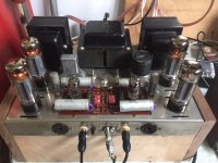
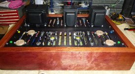
I just realized the photos of the amp on my website are obsolete. I changed the input tubes to 6SN7's (to get rid of the cool looking tube caps, which were grid wires and caused a tiny bit more hum - even though they were shielded with a GND connection at one end), and never re-shot the photos. The schematics are up to date in the calculations link (about half way down the page).
The Ultimate Tube Amplifier?
Last edited:
Thanks again Bob. Nice work. I really wish sometimes that I would have done/do better with documenting things. I made a similar amp a couple years back, 6SN7>6SN7>6BG6GA. Though I did not go to the lengths you did to maximize front end linearity and phase response, just simple parallel section 6SN7 CCS Sunk, cap coupled into CCS forced differential 6SN7 like yours, to output stage very similar as well, neg bias, ac balance...
Of course, reading through your site I see you have far more technical knowledge than I do (yet, ha ha). I like that you took the time to implement the cathode follower buffer. Also, that you were mindful of frequency response, not just as it applied to each stage/miller, but also the 50hz high pass after the 6SN7 (6F8G).
Reading through pages there I see that a lot of your work is centered around phase margin, and keeping it in check. Funny, I am just getting into this. One of the projects that I am doing right now is a pair of small 2 ways, and a sealed 12". The whole system will be actively crossed somewhere between 60-80hz. When I started I was just looking to build a pair of "nice" speakers in the house. I don't have too much experience with speaker building as of yet. Now, as it stands, I am learning about all of this and have project going that keeps phase (of the speakers at least) within 30degrees from 60-20k (not the highest efficiency)
Again, nice work, and thanks for sharing. After having seen so many of the designs on the Web, I am always happy to see one that I as of yet haven't. I saw that you said you have made a lot of SS amps as well. I saw some more guitar amps, and the LM3886, but if you have anything else I would love to see it. Especially if you have any other speaker designs.
Thanks!
The GZ34 rectifier cannot supply enough current to drive both channels to anywhere near full power. Replacing this with normal solid state diodes is mandatory if you want the amp to work as advertised (35 watts per channel).
Oh just saw that post at the top of page. Thank you Eli, I appreciate you taking the time. Yes, I figured if one was to SS alone it would make for perfect opportunity for more LP RC filters. That is if one was leaving everything on this chassis and not adding a larger choke.
Thanks for taking time and posting the pic,
Thanks for taking time and posting the pic,
Thanks for the compliments. Speaker projects remind me of playing the guitar; it's easy to make something that's passable for most people, but very challenging to make a really great speaker. I've always enjoyed the challenge of it. Ultimately I think I'm mostly driven by good music, to do all these projects. This hobby used to seem like an investment in my career, before most of the jobs went to China, and then digital came in and obsoleted much of my analog expertise. But it's still a hobby for me, as it has been since I was in grade school.Thanks again Bob. Nice work. I really wish sometimes that I would have done/do better with documenting things. I made a similar amp a couple years back, 6SN7>6SN7>6BG6GA. Though I did not go to the lengths you did to maximize front end linearity and phase response, just simple parallel section 6SN7 CCS Sunk, cap coupled into CCS forced differential 6SN7 like yours, to output stage very similar as well, neg bias, ac balance...
Of course, reading through your site I see you have far more technical knowledge than I do (yet, ha ha). I like that you took the time to implement the cathode follower buffer. Also, that you were mindful of frequency response, not just as it applied to each stage/miller, but also the 50hz high pass after the 6SN7 (6F8G).
Reading through pages there I see that a lot of your work is centered around phase margin, and keeping it in check. Funny, I am just getting into this. One of the projects that I am doing right now is a pair of small 2 ways, and a sealed 12". The whole system will be actively crossed somewhere between 60-80hz. When I started I was just looking to build a pair of "nice" speakers in the house. I don't have too much experience with speaker building as of yet. Now, as it stands, I am learning about all of this and have project going that keeps phase (of the speakers at least) within 30degrees from 60-20k (not the highest efficiency)
Again, nice work, and thanks for sharing. After having seen so many of the designs on the Web, I am always happy to see one that I as of yet haven't. I saw that you said you have made a lot of SS amps as well. I saw some more guitar amps, and the LM3886, but if you have anything else I would love to see it. Especially if you have any other speaker designs.
Thanks!
Documentation is difficult to get right because things keep changing... Throughout the whole process I keep thinking of better ways to do certain things, and/or I find mistakes in my designs. It's a continuous learning process. I didn't realize I hadn't put the latest schematics of my Musicbox amp up on my website until you asked to see them. When you've got several different projects still getting "finished", it's easy to overlook things.
There's a 24HZ hi-pass after the first triode, but I don't have a 50HZ hi-pass anywhere, in the updated schematics. In the original design (somewhat obsolete schematics further down the page) I did have a 50HZ hi-pass since I knew I was going to use it for above at least 100HZ in my tri-amp'd speaker system. I later changed it down to 24HZ so it could be used anywhere. I have a "tube guru" friend, and wanted to have him "test drive" this amp into his passively crossed over speakers that he thinks are so great (eh), so I needed to do that.
Good evening everyone,
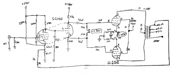
This is the circuit I will be using for an ST-70 clone. the 7199 will be replaced with a 6GH8A and the output tubes will be some form of a sweep tube.
The PCB on the chassis will be replaced with a piece of steel and the 6GH8A and 6CB6s will be wired point to point.
This is the circuit I will be using for an ST-70 clone. the 7199 will be replaced with a 6GH8A and the output tubes will be some form of a sweep tube.
The PCB on the chassis will be replaced with a piece of steel and the 6GH8A and 6CB6s will be wired point to point.
Attachments
Thanks all. After checking, it seems like a crap shoot as far as value...somewhere around 400 is common. So, just because I couldn't bring myself NOT to touch the soldering iron, I did a few things,
new binding posts
new RCA
.01 across AC and Secondary
New Schottky for the bias
Changed feedback to 8 ohms tap
New Ultrafast/soft for the rectifiers
Tomorrow change the PS caps. First will get tuned (lower value), and second will get raised (all I have in shop right now is 1200uf 350V, so 600uf it is)
Also I'll bypass all caps, but probably leave all the ones on board, they all test fine still.
So this puts me 2 hours and about 10$ into it...I can live with that even if it's just for my peace of mind listening until I sell.
The other thing I was thinking about doing, and still might, was individual bias. The Bass IS a bit flabby....
You guys are terrible, someone should have just told me to leave it alone ha ha.
rsumperl, nice. I built one similar few years back, with 7591 outputs. Turned out well. I meant to change the front end around to just an IT loaded triode, something like 1:2, into those drivers. Never got around to it, and sold the amp. There are all kinds of circuits to play with in those manuals...
If you deem the bass to be "loose" you should leave the feedback on 16ohm ( you lessened it by moving to 8 ohm). Instead move your speakers one step lower ( of it was on 8 ohm, move to 4 ohm ).Thanks all. After checking, it seems like a crap shoot as far as value...somewhere around 400 is common. So, just because I couldn't bring myself NOT to touch the soldering iron, I did a few things,
new binding posts
new RCA
.01 across AC and Secondary
New Schottky for the bias
Changed feedback to 8 ohms tap
New Ultrafast/soft for the rectifiers
Tomorrow change the PS caps. First will get tuned (lower value), and second will get raised (all I have in shop right now is 1200uf 350V, so 600uf it is)
Also I'll bypass all caps, but probably leave all the ones on board, they all test fine still.
So this puts me 2 hours and about 10$ into it...I can live with that even if it's just for my peace of mind listening until I sell.
The other thing I was thinking about doing, and still might, was individual bias. The Bass IS a bit flabby....
You guys are terrible, someone should have just told me to leave it alone ha ha.
rsumperl, nice. I built one similar few years back, with 7591 outputs. Turned out well. I meant to change the front end around to just an IT loaded triode, something like 1:2, into those drivers. Never got around to it, and sold the amp. There are all kinds of circuits to play with in those manuals...
Individual bias won't help, it will just tempt you to run unbalanced tubes.
Ditto on the 5AR4 and the stock power transformer - my ol' Dynaco 70 had some audible compression at higher volume levels. This was even with a SDS power supply board and a Triode Electronics input PCB.
Hi Peter. As for the feedback, yes that was my intention was to lessen it a bit. Also the 8ohm speaker on 4 Ohm tap (higher primary reflection, higher DF) trick I use as well. In conjunction I believe better response than with either one alone. As for individual bias, I see that as a help, for the bass and overall. Less imbalance in a balanced circuit (in the PP stage) is always good. I get what you're saying, but believe me I won't be tempted. I don't have any other el34 in the shop. Although not sure what you see as bad about that anyhow. I think for the casual listener, and especially if this thing goes to someone only just learning about tubes, it is good for them to be able to use whatever quad they like, and learn about individual bias / transformer balance. The dynaco circuit may me so that little is gained balancing the OPT, but it sure won't hurt...
Well, I did all I think I'll do for now. The power supply seems absolutely fine (if not the best circuit), especially since I disconnected 5v 1.9A, and because I dropped tuning cap from 30uf to 10uf poly. All the rest of the caps tested fine, it looks like someone did replace them, with one of the aftermarket cans. I took the now unhooked 30uf and paralleled it with the 20 after choke so that now it is 10, 1.5H, 50. That and the feedback change, definite improvement in bass...oh and I'm sure the new bias caps helped too, now 120uf instead of 50, each. Almost a shame to sell. Thanks guys
Well, I did it
So through this short thread I always was finding it funny, how many replied with "well you should definitely do this" or "make sure you do that". I had stressed at the start that I wasn't planning on doing anything with it, just curious about some of your opinions on the sound because there are a lot of guys here I respect.
Well, maybe you all just knew better...We all have varying levels of this thing called "have to work on it", I guess.
The Fisher sold, and more than paid for the two if the amps. So I decided what the hell, I'll keep the Dynaco for a minute. And since I was keeping it, well, "have to work on it"
I think the original driver board is not bad for what it is, not the best phase splitter, but still good performance. It's every bit as good as A LOT OF the aftermarket boards out there. So I decided to keep the Original Circuit for the most part, but to do it a little justice, with a pile of parts that weren't slated for any other projects here in the shop. Here's the list of changes:
Oh, and ALL caps are film, not a single 'lytic in here anymore
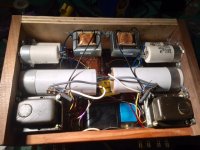
Power Supply:
Bootstrapped 5V winding to primary
SS Rect. with UF/US diodes
First Cap lowered to 10uf
Then HT rail splits to left and right channel, each channel is
5H>160uf>15k>10H>27uf>39k>27uf. All caps bypassed with .5 and .01
All voltages at or within 10V of original spec
Bias Supply:
SS Rect. with UF/US diode
20uf>the stock 1.75H choke>30H choke>200uf>total adjustment pot>individual balance pots.
Works Great, I can easily DC balance output tubes now.
Driver Board:
Split power rails for the split HT power rail.
Replaced coupling caps with nice NOS Westcap .22
Replaced anything else out of spec. Most all of it was still fine.
Other random stuff, some of which I mentioned previously:
New I/O Jacks and binding posts
All extra wires (for stock preamp) disconnected
Front Octal jacks now test points for EACH output tube.
Oh, each output has it's own 10ohm cathode, obviously.
Oh, and the whole thing is now Star Greound to One Point
I'm probably forgetting a few things, but yeah. She sounds nice. Not amazing, but pretty darned nice for 2 days of spare time work, and about 50$ worth of parts.
Who knows, maybe someday someone will search out this thread. The bias/balance and the split power supply are mods that I have not seen anywhere else. Not that they're anything special, just different stuff for some other builder to find. Thanks Guys,
So through this short thread I always was finding it funny, how many replied with "well you should definitely do this" or "make sure you do that". I had stressed at the start that I wasn't planning on doing anything with it, just curious about some of your opinions on the sound because there are a lot of guys here I respect.
Well, maybe you all just knew better...We all have varying levels of this thing called "have to work on it", I guess.
The Fisher sold, and more than paid for the two if the amps. So I decided what the hell, I'll keep the Dynaco for a minute. And since I was keeping it, well, "have to work on it"
I think the original driver board is not bad for what it is, not the best phase splitter, but still good performance. It's every bit as good as A LOT OF the aftermarket boards out there. So I decided to keep the Original Circuit for the most part, but to do it a little justice, with a pile of parts that weren't slated for any other projects here in the shop. Here's the list of changes:
Oh, and ALL caps are film, not a single 'lytic in here anymore
Power Supply:
Bootstrapped 5V winding to primary
SS Rect. with UF/US diodes
First Cap lowered to 10uf
Then HT rail splits to left and right channel, each channel is
5H>160uf>15k>10H>27uf>39k>27uf. All caps bypassed with .5 and .01
All voltages at or within 10V of original spec
Bias Supply:
SS Rect. with UF/US diode
20uf>the stock 1.75H choke>30H choke>200uf>total adjustment pot>individual balance pots.
Works Great, I can easily DC balance output tubes now.
Driver Board:
Split power rails for the split HT power rail.
Replaced coupling caps with nice NOS Westcap .22
Replaced anything else out of spec. Most all of it was still fine.
Other random stuff, some of which I mentioned previously:
New I/O Jacks and binding posts
All extra wires (for stock preamp) disconnected
Front Octal jacks now test points for EACH output tube.
Oh, each output has it's own 10ohm cathode, obviously.
Oh, and the whole thing is now Star Greound to One Point
I'm probably forgetting a few things, but yeah. She sounds nice. Not amazing, but pretty darned nice for 2 days of spare time work, and about 50$ worth of parts.
Who knows, maybe someday someone will search out this thread. The bias/balance and the split power supply are mods that I have not seen anywhere else. Not that they're anything special, just different stuff for some other builder to find. Thanks Guys,
Attachments
Thanks! Usually I take a bit more time to make everything under the hood more tidy, but since I was staying original circuit, and it was all point to point except the driver board originally, i took that as an excuse to do the same with my wiring ha ha...electrically it's sound, and I suppose that's what matters 🙂
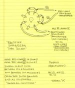
Dynaco PC3A driver boards with 6GH8A
Hello I'm making an integrated (passive) PP amp with dynaco driver board modified for 6GH8A tubes unstead of 7199.
My transformers are from a Fisher 800C and output are too from the same Fisher receiver.
Power supply is from the same design from Fisher, voltage doubler, solid state rectifier, and caps, CRC arrangement, with B+ at 440vdc , screen at 388vdc, driver board at 360vdc and 356 vdc respectively.
Bias is -60vdc and ajustable for each tubes .
Feedback to the driver board from 16 ohms tap and screen tap from Dynaco design.
I get the amp work , but as soon as i crank volume and with bass content, it seem that the amp oscillate and goes to low frequency bounce with bass frequency, weird?
I'm thinking that DC volts for driver boards is a bit high?
grid resistors are 10kohms for each 6L6.
Each 6l6 is with a 10 ohms cathode, so 0,45 volts there biases the 6L6 fine.
This is not my first project using Dynaco ( Triode Elect.) driver boards with Heathkit outputs and power transformers using 6L6's.
voltages in circles are actuals volts with the amp in test, primary is 117vac.
Thanks
Attachments
as soon as i crank volume and with bass content, it seem that the amp oscillate
and goes to low frequency bounce with bass frequency.
Is the OT secondary winding's common lead connected to ground? It isn't in your sketch.
Last edited:
- Home
- Amplifiers
- Tubes / Valves
- Dynaco ST-70, Original or Mod?