At this point you really should dissemble and take better pictures, also test in stages.
Yes I know it's work but there are steps to debugging.
Yes I know it's work but there are steps to debugging.
OP is in Boulder, CO
6L6...... I'm just browsing the threads (long time, no chat!)
I noticed the OP for this thread is in Boulder. Might be worthwhile for him to drag one of his monoblocks down to you, for you to inspect. (Or perhaps, vice versa..... Boulder is beautiful this time of the year.... Go Buff football!)
6L6...... I'm just browsing the threads (long time, no chat!)
I noticed the OP for this thread is in Boulder. Might be worthwhile for him to drag one of his monoblocks down to you, for you to inspect. (Or perhaps, vice versa..... Boulder is beautiful this time of the year.... Go Buff football!)
Pjanda1.....
Gees--I typed up a long reply to this thread--and them apparently blew it away before it got posted....
Here is the short version. Please ponder:
Your amp board require two "opposing" rail voltages. Effectively, you have two power supplies in each monoblock. One is intended to provide the positive rail voltage, and the second supply the negative rail. It is very important to wire these two power supplies correctly:
You connect the POSITIVE output of one of the supply capacitor banks to the positive rail, and this power supply NEGATIVE to chassis ground..... (This becomes your positive rail voltage with respect to ground)
You connect the NEGATIVE output of the other power supply capacitor banks to the negative rail, and this power supply POSITIVE output to chassis ground. (This gives you the negative rail with respect to ground)
If you do the above, you have properly "oriented" the power supplies, with each providing about the same voltage to each rail--with a + rail, and a - rail.
IF HOWEVER, you set your power supplies up to "buck" one another, when you measure your "rail-to-rail" voltage it would be very small (in theory zero, if all power supply components were identical).
If you need to confirm on you monoblocks, take one monoblock and disconnect both "halves" of the power supply from the amp boards and (importantly) from any common ground. Measure the output of each power supply to confirm you have the proper polarities, and connect one of the power supply NEGATIVE outputs to the POSITIVE output of the other supply (e.g. these will become your common power supply gorund. If you then get the proper + and - rail voltages, you have resolved this potential issue. Rewire the power supplies to the monoblock amp board once you have confirmed voltages and polarities. Power up first with your Variac, and monitor voltages and biases as you go.
Take it from an experienced builder--"build in stages"..... For these amps, do the "two" power supplies first, and confirm output voltages and polarities for each of them. Then, build ONE amp board, power it up (Variac in place) and then set biases accordingly. If everything checks OK, finish the second amp board and wire it in--no sense "torching" both amp boards in one blazing grand finale....(!)
Let me know if this helps. If not, I'll continue to ponder.....
Last edited:
Hello CanAm!!
Good advice all around. I'd be more than happy to help him out, after all, he got the chassis from me... 🙂 🙂 🙂
This is not particularly clear - I'm not sure if you have the rectifiers to caps wired properly after reading this.
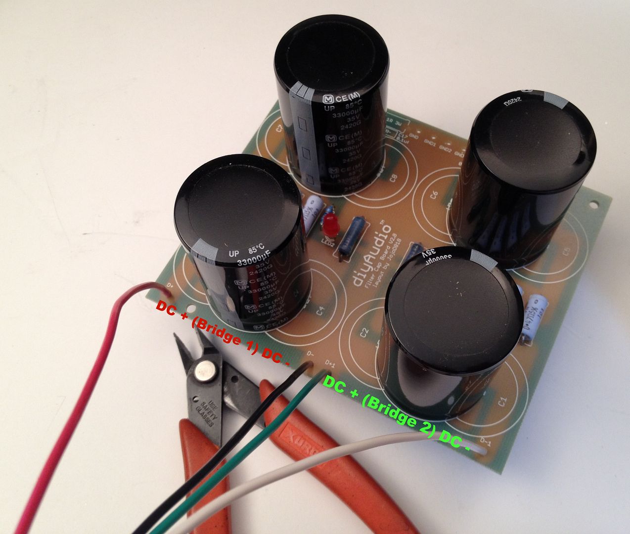
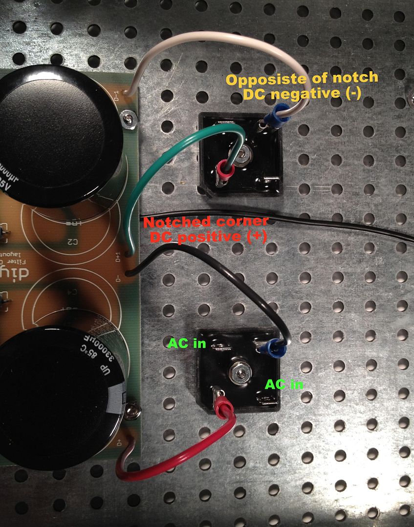
This may help - (click the images is they appear smushed)
Good advice all around. I'd be more than happy to help him out, after all, he got the chassis from me... 🙂 🙂 🙂
There are two rectifiers--one is tough to see. (And it is impossible to see the soft start thermistor wiring that is between them--it is all under the transformer leads). Each rectifier is wired like the one you can see: with a blue coming off of the positive of the rectifier and a green off the negative. That is why you see the blue to the positive rail and a green to the negative rail, each from different bridges. The corresponding green and blue are tucked back to the ground between the caps.
This is not particularly clear - I'm not sure if you have the rectifiers to caps wired properly after reading this.
This may help - (click the images is they appear smushed)
Last edited:
Jim.... 6L6..... I always admire your postings, your construction, and your diyaudio photo's. You always get a PASSing grade in my book!
Thanks!!
The Pass Sony Vfet amp is currently under construction, I applied power to a channel yesterday, and the magic smoke remained inside... a good omen!
The Pass Sony Vfet amp is currently under construction, I applied power to a channel yesterday, and the magic smoke remained inside... a good omen!
Pjanda1..... I had a chance to give your pics a closer look. It looks as though you do have the correct power supply configuration (+ rail, common ground, and - rail). As such you can disregard my long-winded diatribe, a few postings ago.
Curious though..... have you ever gotten your F5's running? Did you figure out the problem?
Curious though..... have you ever gotten your F5's running? Did you figure out the problem?
My frustration keeps pushing me away from these. As I indicated I would be, I was too lazy to disassemble the rectifier bit, but I thought of another way to test them. I have two 8 ohm 100w resistors, so I hooked those up instead of the CRCs. I took it up to 100v or so on the variac, and the rectifiers/transformers worked just fine (good +/- voltages). So the problem is definitely in the CRC filter.
Is there a chance that these caps don't like to be clamped down tight? All I have left at this point is starting the CRC bit over again, but as you can see, I don't have too much space for other options.
6L6: I figured you had had it with me since you weren't responding to my email! But I'll happily drive them down sometime if you want to have a look. I haven't been in Denver for minutes now . . .
Paul
Pjanda1 - Sorry you thought that! I'm always happy to help and would love to assist in any way. I thought I responded to the emails... Maybe they didn't go through? dunno.
Let's figure out a time to meet and get your amps working!
Let's figure out a time to meet and get your amps working!
My frustration keeps pushing me away from these. As I indicated I would be, I was too lazy to disassemble the rectifier bit, but I thought of another way to test them. I have two 8 ohm 100w resistors, so I hooked those up instead of the CRCs. I took it up to 100v or so on the variac, and the rectifiers/transformers worked just fine (good +/- voltages). So the problem is definitely in the CRC filter.
Do you have the CRC assembly DISCONNECTED from the two amp boards? If not, then you've only tested about 5% of the amp, leaving both the PS filters and the amp boards as potential suspects.
If you DO have the CRC assembly disconnected from the two amp boards, take an ohmmeter (assuming you have a good multimeter.....) and place the meter leads to each capacitor. Initially, you should see a low resistance, with the resistance increasing over time. If the meter reads low resistance--and stays that way--you probably have a shorted capacitor (although having one should have given you "fireworks" when you initially put line voltage to the transformer primary). On the other hand, if the meter initially reads high resistance and stays high, you have an open capacitor.
Good luck. Jim (6L6) can help, if you are baffled/lazy/disinterested(!). The F5 is a simple amp, and not "rocket science" to troubleshoot. Consider this to be an opportunity to learn some more electronics.
Yeah, the CRC assembly tests fine with the ohm meter. But it is definitely the problem in some form. To recap (hah): the rectifiers work fine not connected to the caps, the thing behaves the same with or without the signal board connected.
I finally got it to Jim's today. I thought some folks might be amused to hear about the issues.
First, I was evidently wrong about it not working with the PSs connected. All of the problems were on the signal board.
1) The feedback resistors were in the wrong holes. They sure looked like the right holes. Jim was darn sharp to catch this.
2) I had crushed one thermistor. I'll be mounting them differently.
3) I had the bias pots cranked all the way up rather than down. I thought all pots went the same way! Turns out, not.
4) I had the gate stopper resistors on the wrong legs of the outputs. I honestly have no idea how I goofed this up.
5) I'll be using more flexible umbilicals to the outputs.
Moral of the story: it is hard to build stuff when you are generally tired and distracted, and when you take breaks of a few months during the process.
Thanks to Jim's patience and help, I'll have them up and running soon!
Paul
In Paul's defense, it really was presenting like a PSU issue... It took about an hour exhausting the PSU possibilities before things were suspected further down.
1) I'm actually surprised I caught this one, it was literally a glance when looking for something else completely, and something about the traces didn't look quite right... I had to look at a image of the PCB traces to determine what was proper. The PCB has holes for resistors the size of the Panasonic 3W that we all know and love, and spacing for something much smaller, like a square-body resistor that needs a heatsink. Anyway, at first look, where he mounded the resistors seemed good.
2) Probably crushed one, need to check it.
3) Believe me, you are not the first one to have done that, and you won't be the last... 🙂
4) The pinout is not intuitive, and the Mosfet schematic symbol is drawn in a way that having the gate in the middle seems logical. Completely understandable error.
5) Yes, in this case flexible is important.
I think one of the amps is actually working properly, the gatestoppers need to be moved and the flying leads re-dressed, but I honestly believe that one will start right up.
It was really nice having you over today, I love working on projects like this!
Last edited:
Pjanda1: Re: "First, I was evidently wrong about it not working with the PSs connected. All of the problems were on the signal board."
Yep....as I had recommended in Post 52. Fully disconnecting the power supply board from the audio boards could have "helped you early" in narrowing down your problem......
Glad, too, that Jim (6L6) and you were able to identify the plethora of issues you had...... Lessons learned for the future.....
It's always good to "build in steps" if new to the design:
1. Wire the transformer primary/line side, first.... Test using the bulb tester (or variac) and confirm your secondary windings' AC voltages.
2. Wire the remainder of the power supply (caps, chokes, filter resistors, bleeders) next.... Test again, using the bulb tester (or variac) and confirm your power supply output DC voltages..... (should be a little higher than your expected "loaded" rail voltages, and about 1.414 times higher than the AC voltages noted in step 1, above....)
3. Only build ONE amp channel. Check your work, resistor values, any capacitor polarities, bias pot settings, and then connect to the power supply (and perhaps initially fuse both rails as another safeguard). Ground (short) the input. Power up the single channel (using the bulb tester or variac). Confirm voltages and component "temps". Connect an audio source and confirm ops.
(Step 3, above, prevents you from destroying two audio boards/channels/parts if you only build one channel first. It also saves you the second channel's parts for troubleshooting and repairing the first channel, if needed.......)
4. Duplicate the operational audio board to build the second..... Hook to the PSU and press on!
Most of us make mistakes, and learn best by them. Good job of troubleshooting, Jim!
Last edited:
They are running and sounding great! Thanks, Jim especially, for the help!
I tried to get the outputs set upright, as you'd expect. But even with the new cable it wasn't going to happen. I had a bit of an oversight thinking that the 5x18g cable would be fine for the mosfets and the thermistors. Of course it fit the mosfet holes fine on the pcb, but I had to dremel the solid core down to get it into the thermistor holes.
I honestly thought these heatsinks might be too small, but biased up to 1.3A, they are doing great going on a few hours now.
Every amp I build I swear that next time I'll use a chassis that has plenty of room to spare. But man these look cute.
They sound great too! I hadn't had a diy amp in the system for far too long, as the only tube amp I have left has been so noisy. These are incredibly honest amps. Compared to the junky Sonance that was taking up space, they sound better in every way. The bass has actual notes, now!
These do not sound like the F1s that have been in recently or my SE tube amp. They sound much like one of my favorite amps of all time: a 6V6 triode push pull circuit. Except that those amps made a whopping 3 watts and had a 40lb power supply that buzzed, even with a 15lb input choke. So far, the F5s are as well behaved as I had dreamed they might be!
Thanks again,
Paul
Attachments
- Status
- Not open for further replies.
- Home
- Amplifiers
- Pass Labs
- How did I goof up these F5s?