Hi Everyone,
I've built a musical instrument that works OK but could do with an ADSR envelope module to shape the output of the rhythm pulses as they don't seem to have enough punch.
I have found some circuits for synthesizers but they run off +/-18 volts and this is far too much for my instrument since it is portable and isn't connected to a wall socket. My electronics run off a 9 volt battery and the components are chosen to keep consumation down to a minimum.
Does anyone know of a simple ADSR design running off of 9V (or less) that could be used for my project? Any suggestions greatfully appreciated. Thanks.
Vielle568
Ka-ching!
Original topic, go about halfway down: electro-music.com :: View topic - What are all the ADSR's out there to build?
Hope that helps
Original topic, go about halfway down: electro-music.com :: View topic - What are all the ADSR's out there to build?
Hope that helps
Hi Test Electrix,
Thanks for all the the ADSR schematics you sent me. I'll try breadboarding the circuit and see what I come up with. The only minor problem I see with the schematic is that it requires +/- 9V and all my stuff is running off of a single 9V supply with one of the op amp lines biased at 4,5V. I can probably do the same thing and see what happens. I'll also change the IC for a TL064 since it draws far less power.
The output signal will then be used to control a VCA that will shape the audio signals (or at least that's what I hope will happen). I guess I'll have to wait and see. I'll let you know how I get on...
Thank's again for your help.
vielle568
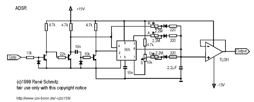
There is another type based on cmos switches and a 555.
you can find it here along with some other cool stuff. i have built the diode ladder filter and the moog filter and they are great.
Synth DIY
you would probably have to change the transistor resistors to a lower value so the +15v would work at +9 v
and you can use your own 9v output opamps or whatever instead of those bipolar ones.
Last edited:
Hi Neutron7,
That's a nice site and the schematic looks good too. You're probably right, if I change the resistor values for the transistors the circuit can be brought down to 9V. I can get away with one op amp and a TL061 will use less current. There are certain superfluous details of the circuit that I can omit all together and what's left is pretty straightforward.
Thanks for your help. I'm currently waiting for some components in the mail but soon I'll be back on track making the modifications to my instrument.
Vielle568
does it work now ?
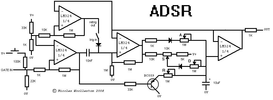
Your firs schematic is quite similar to this one :http://www.uni-bonn.de/~uzs159/adsr2.png
Your firs schematic is quite similar to this one :http://www.uni-bonn.de/~uzs159/adsr2.png
hi guys i am new for these things and i wanna build adsr for my synthesizer. I want to ask what is gate for this circuit. I mean is this a switch or i should make oscillator and oscillator's output will be gate??
Last edited:
The gate signal starts the generation of the ADSR envelope. It is normally supplied by your keyboard or sequencer to signal the ADSR that a key has been pressed (or sequenced), or a note on signal has been received via MIDI.
It is a voltage level signal that is normally low, a quarter of a volt or less, usually 0 volts. When a key is pressed the gate signal will go high, 3 volts or more, and remain there until the key is released (or a MIDI note off command is received). The voltage values of the gate low and gate high signals depend on the rest of your synthesizer hardware. Low = 0 volts is common, but high can be 5 to 15 volts, with 5 or 10 volts (ARP and MOOG) being the most common.
This circuit will generate a timed series of events producing a control voltage that is usually applied to a VCA or VCF to modulate the audio signal.
hi guys i am new for these things and i wanna build adsr for my synthesizer. I want to ask what is gate for this circuit. I mean is this a switch or i should make oscillator and oscillator's output will be gate??
A "gate" is a signal voltage, the ADSR changes that signal.
Normally, the keyboard of the synth has a gate signal output, together with a cv signal output. The gate signal indicates here, in case of a keyboard, when a key is pushed down and when its released. The cv signal is a voltage value for what key is being played. More info here: https://en.wikipedia.org/wiki/CV/gate
Read page 3 for full understanding of gate signals and how ADSR's change that signal..
http://www.doepfer.de/a100_man/A140_man.pdf
Other things that can be used as gate signals are LFO's, so yes you could build an oscillator and use its output as gate signal, but make sure it goes low enough in frequency, iow sub audio, a few tents of seconds to a few minutes is perfect. Triggering an ADSR with audio frequencies results in just a continuous signal or just mayhem, depending on the circuit used, witch could be cool.
Other useful gate signals are logic circuits, other envelopes, S&H, foot switches, ribbon controllers, joysticks, comperators. Basically anything goes.
Btw this schematic is an ADR, but easy to build.
And last but not least: Download the free Clavia G2 demo software here Downloads for Nord Modular G2 | Nord Keyboards and start patching. Modular synths are easiest to understand, you just start with 1 module turn the knobs see what it does, then ad an other module.
This is a great site to get to learn synths: https://rhordijk.home.xs4all.nl/G2Pages/
- Status
- Not open for further replies.
- Home
- Live Sound
- Instruments and Amps
- ADSR schematic