All i am asking is, that open loop gain is already complicated enuf, so why should one still raise confusion by making feedback depend on frequency, too? I rather reduce feedback a little: Distortion numbers stated in the datasheet indicate, that cutting feedback by two will not result in too much distortion.Grasso, you're missing the point.
Thank you for the heads-up!You are right that to get good performance, you need good decoupling.
All i am asking is, that open loop gain is already complicated enuf, so why should one still raise confusion by making feedback depend on frequency, too? I rather reduce feedback a little: Distortion numbers stated in the datasheet indicate, that cutting feedback by two will not result in too much distortion.
The reason for the "complicated" feedback network is that the LM3886 runs out of gain as the output swings near the negative rail. This results in quasi-oscillation near the negative rail. To combat this, add Cc. Now this mucks up the transient response, so you add Rf2 and Cf to address this. Those three components allow the amplifier to have a fighting chance of meeting the specs in the data sheet. It's three components. They're all described in the data sheet. It really isn't all that hard but it does require you to actually make it past page one of the data sheet.
Tom
Why are those ghost parts? Why is there no "build it like that with good components, and it will work, guaranteed" circuit plus PCB in the datasheet? I as a very-small-scale builder do not apply a chip in order to have to run extensive stability tests.
Why are those ghost parts? Why is there no "build it like that with good components, and it will work, guaranteed" circuit plus PCB in the datasheet? I as a very-small-scale builder do not apply a chip in order to have to run extensive stability tests.
If you buy a proven pcb that's been around a while, you have a good chance of a working amp when complete.
Why are those ghost parts? Why is there no "build it like that with good components, and it will work, guaranteed" circuit plus PCB in the datasheet? I as a very-small-scale builder do not apply a chip in order to have to run extensive stability tests.
First off, the components I mentioned (Cc, Rf1, Rf2), the Thiele Network, Zobel Network, and decoupling are all discussed in the LM3886 data sheet. You can actually make a good circuit with the information given in the data sheet. That's what I did with my LM3886DR. The only thing I add which isn't in the data sheet is the RF input filter.
You do occasionally see a "suggested layout" in the data sheet of various electronic parts. It seems most common among voltage regulators. I guess for other types of ICs it is assumed that the circuit designer and layout designer are able to translate the information given in the data sheet into the schematic and layout.
Tom
"Occasionally, current in the output leads (which function as antennas) can be coupled through the air to the amplifier input, resulting in high-frequency oscillation"
So Cc has to short hf noise on both inputs + and -.
Guess the -3db freq depends internal circuitry? And Ri if source imp is high?
So maybe it is exprimental. Should fcc be smaller or higher than fsf? To me they seem independent as they are both lp. Together 2. Order. And a 2 order filter can have different step responses.
The formula for calculating the Fc of the negative feedback low pass filter on page 8 in the LM3886 TI datasheet says:
fc= [Rf1*Rf2*(s+1/Rf2*Cf)]/[(Rf1+Rf2)*(s+1/Cf(Rf1+Rf2))]
My question is, what is "s" referring to? QUOTE]
If you still wonder the wikipedia article on Bode plots explains it :
https://en.wikipedia.org/wiki/Bode_plot
Used a lot in the olden days when SPICE was not conceived.
Still usefull for rule of tumb engeneering! The hardcore old school use normalized omega instead of f, of course.
Found a series of MIT lectures:
https://www.youtube.com/watch?v=ToEFkUxFURg&list=PLUl4u3cNGP62in17jH_DiJMkCGNM6Xni-
At 20:40 the feedback figure is displayed. There f is the anotation of the feedback transfer function.
So then fc(s) makes sense. Nowadays that is quite confusing🙂
By the way. A lot to be learnt from those old school lessons!
Hi all, So is the formula below working? fc= [Rf1*Rf2*(s+1/Rf2*Cf)]/[(Rf1+Rf2)*(s+1/Cf(Rf1+Rf2))] And is s=6,28? If yes, then this formula is not working, It's giving stupid result. My Rf1=25k and Rf2=10k, because My Ri=690. I don't know what Cf capacitance should I use.
Hi all, So is the formula below working? fc= [Rf1*Rf2*(s+1/Rf2*Cf)]/[(Rf1+Rf2)*(s+1/Cf(Rf1+Rf2))] And is s=6,28? If yes, then this formula is not working, It's giving stupid result. My Rf1=25k and Rf2=10k, because My Ri=690. I don't know what Cf capacitance should I use.
How did you come up with s=6.28?
How did you come up with s=6.28?
6.28 = 2*pi
I'm not otherwise following the thread to help much more, but I do like that you're trying to understand what's going on. 🙂
You have to evaluate the formula and find S that gives fc = 1/root(2) = 0,707 or -3 dB
The 20 hour MIT lessons will explain
The 20 hour MIT lessons will explain
Yes, I meant if this is 2*pi, because, from what I can deduce, there were two versions, 2*pi and zero.
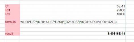
All maths is cool but how do I calculate the size of the capacitor? I put in Excel and the result is in in pHz 🙂 I'm not very experienced with Excel, maybe put sth. wrong.
Attaching the picture
All maths is cool but how do I calculate the size of the capacitor? I put in Excel and the result is in in pHz 🙂 I'm not very experienced with Excel, maybe put sth. wrong.
Attaching the picture
Attachments
Its more complicated than that. The number may be 1 or 1/2 I never remember
Transferfunction H(s) = A/(1+fc) where fc is the feedback transfer function. A is the amplification
Use spice and simulate as tomchr suggested instead.
Transferfunction H(s) = A/(1+fc) where fc is the feedback transfer function. A is the amplification
Use spice and simulate as tomchr suggested instead.
Last edited:
Maybe I could somehow get around 🙂
While in original circuit Rf2=20k and Cf=50pf and in my circuit Rf2=10k (2x smaller), then maybe my Cf should be double, that is 100pF?
While in original circuit Rf2=20k and Cf=50pf and in my circuit Rf2=10k (2x smaller), then maybe my Cf should be double, that is 100pF?
Last edited:
Torgeirs, will the Electronics Workbench show this too? There is tda2030 in it. It should be the same result.
Maybe? Who knows without evaluating the expresion. This is not a clean 1. order filter...
By the way you can use excel, but you have to use complex number formula. So it gets kind of messy.
You can also do it the hard way: Put in different values and measure. Half and double value of Cf is good starting points.
By the way you can use excel, but you have to use complex number formula. So it gets kind of messy.
You can also do it the hard way: Put in different values and measure. Half and double value of Cf is good starting points.
I'm wondering if this Cf capacitor is changing something significantly in my amp, because for 37x gain this is 100kHz bandwidth amplifier. I'm afraid not 🙂
Sorry, Piotr missed a post. So Maybe? refered to the doubling og Cf
Yes, the Cf is interacting with the GBW product. So it is spesific to the amps GBW product.
And remember from LM3886 pdf:
Interaction may occur for components whose reactances are in close proximity to one another. One example would be the coupling capacitor, CC, and the compensation capacitor, Cf. These two components act as
low impedances to certain frequencies which will couple signals from the input to the output.
Torgeirs, I'm not sure what this "interaction" means? Resonant filtering with high frequency boost? If yes, this is not predictable, because input series resistance is unknown, it can change when there is pot in the output of the previous stage (like preamp). And this changing series resistance is interacting with Cc.
I just read: Artifacts may occur, you may have to change values if you are unlucy and the artifact is present.
I do not know if you can model the caps in spice so you can predict the behaviour.
The bottom line. Changing the values may give artifacts or unstability.
I do not know if you can model the caps in spice so you can predict the behaviour.
The bottom line. Changing the values may give artifacts or unstability.
- Status
- Not open for further replies.
- Home
- Amplifiers
- Chip Amps
- LM3886 - Calculating Fc for low pass NFB filter