I just uploaded a schematic of a circuit, and I need some help with it. The LED is a two color indicator, that is powered from the 6.3VAC filament supply for a 12AX7 tube. The LED indicates the condition of a "fat" switch that feeds the plates, and it is controlled by a switch operated SPDT relay. The schematic only shows the indicator circuit. This all worked before I had to change the ground reference. The two 100 ohm resistors used to connect directly to ground. How do I get the indicator working with this new arrangement?
Attachments
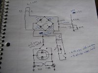
I think you want the emitters tied to the common anode tap on the bridge rectifier instead of "ground."
You are referring to where the two 100 ohm resistors are connected o each other?I think you want the emitters tied to the common anode tap on the bridge rectifier instead of "ground."
I think you want the emitters tied to the common anode tap on the bridge rectifier instead of "ground."
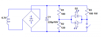
I'd say the emitters should go to the junction of the two 100R resistors, not to the rectifiers.
You are referring to where the two 100 ohm resistors are connected o each other?
No. Perhaps it's clearer to specify the negative side of the filter cap on the relay coil power supply, so the LED circuit is powered by that same power supply.
I got a lot of hum this way. The light worked, though.I'd say the emitters should go to the junction of the two 100R resistors, not to the rectifiers.
Indeed, like this 🙂I think you want the emitters tied to the common anode tap on the bridge rectifier instead of "ground."
Mona
Attachments
too much hum this way, too.No. Perhaps it's clearer to specify the negative side of the filter cap on the relay coil power supply, so the LED circuit is powered by that same power supply.
Well, I think we need to see the whole schematic then. And if this thread pertains to a musical instrument amp, then it's in the wrong forum.
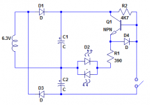
The filament for the tube is on this circuit, too. The relay is used to change the plate voltage. The LED switches green to red when the plate voltage on the tube is changed to a higher value. More voltage to the plates gives a temporary fatter sound. I need the artificial center tap to reference the ground on the filament to eliminate hum.In fact, you can get rid of most of the components, relay, etc, and leave the indicator circuit floating: see example below
Where is the right one then? Sorry for intruding.Well, I think we need to see the whole schematic then. And if this thread pertains to a musical instrument amp, then it's in the wrong forum.
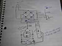
In fact, it is an additional argument for using a completely floating circuit, like the ones I proposed, but I cannot be sure as you seem intent on withholding information, and even the partial sketch you provided is barely legible.The filament for the tube is on this circuit, too. The relay is used to change the plate voltage. The LED switches green to red when the plate voltage on the tube is changed to a higher value. More voltage to the plates gives a temporary fatter sound. I need the artificial center tap to reference the ground on the filament to eliminate hum.
No wonder you got no satisfactory answer on the other forum....
The hole LED+relais circuit is floating and the heaters are connected to a center grounded source.From where you expect hum 😕It causes hum problems this way, too.
Mona
I have no reason to withhold the whole schematic. I just thought there would be an easy fix to it. Is there another forum where we could discuss this? II have it posted in the "all about circuits" forum here: 2.1VDC forward voltage needed for LED. What do I need to do to the circuit shown? | Page 2In fact, it is an additional argument for using a completely floating circuit, like the ones I proposed, but I cannot be sure as you seem intent on withholding information, and even the partial sketch you provided is barely legible.
No wonder you got no satisfactory answer on the other forum....
- Home
- Amplifiers
- Tubes / Valves
- indicator light using filament 6.3VAC voltage