Tim , can I (and if I can , where ?) ask you few questions , related to one sad specimen (due to rough history) of EAR 859 , I'm resurrecting for a friend ?
TIA
TIA
I will not say why there are those caps. Nothing to do with the drivers being able to drive speakers alone.
I can't imagine that this was the reason. One clue though is that Fisher used the same caps in their cathode follower.
500 watt 529 amp
i have a 300watt design that uses just a pair of output tubes....
i figure that if i had to use a lot of tubes to get that power, why bother?
what fisher model was that SY?
I think it was the 50A, but I'm going off memory here.
It can be done with one pair at high voltages. I did on with a pair of 833 but it becomes impossible to achieve the high frequency performance I eat.
The 10 pieces of Pl509 arranged a safe method gives me the 60 KHz at full power down to 20 HZ full power. Also I can still maintain very low distortion.
There are no valves that will switch 10 amps at 50 volt saturation. 833 needed 2,000 volt on the anodes. And about 15 K plate to plate load.
The output transformer needs high insulation and weighed 20 Kg.

But in the Fisher, the capacitors shunt the AC signal to the grid, while in the MB-3045, they are connected between the driver and output tubes' cathode windings.
But in both cases, you have 1:1 windings in the CF circuit which are connected primary to secondary via the caps. The Fisher doesn't use unity coupling in the output stage, so the secondary of the CF's transformer is connected differently to the output stage.
I wish Tim weren't reticent about revealing the function. I have a guess, but will admit that it's purely a guess. The rest of the 3045 circuit is pretty clear and, IMO, quite well done.
I wish Tim weren't reticent about revealing the function. I have a guess, but will admit that it's purely a guess. The rest of the 3045 circuit is pretty clear and, IMO, quite well done.
In the case of the Fisher 50A having worked on a number of them and observing the very poor quality of the IT used I concluded that the caps were there to shunt the rather substantial leakage inductance of that transformer. I can attest to the fact that if those caps are bad or omitted the amplifier will oscillate into most real world speaker loads and IIRC resistive loads as well. (In fact it has a well deserved reputation for instability) Can't speak to Tim's reasons of course.
I use ITs in all of my current designs, perhaps becoming a wee bit notorious for that, so perhaps I know a little something about it.. (Or not)
I use ITs in all of my current designs, perhaps becoming a wee bit notorious for that, so perhaps I know a little something about it.. (Or not)
Right, the caps in the Fisher are necessary to compensate for the low-quality driver transformer. But does the same apply to the Luxman OPT?
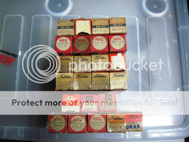
i have a quad of the 6R-A8 but they are not for sale, from time to time,
we discover shops or warehouses that were long forgotten.....
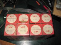
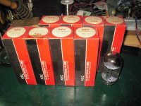
my collection of Japanese tubes. i have more that are not boxed....
the 6R-HH1/2/8 and the 6r-r8 pentodes...
Japanese TV horizontal and vertical scanning tubes....
these are not for sale though....
the 6r-p22 is a direct sul for the 6bq5 i think....
we discover shops or warehouses that were long forgotten.....
my collection of Japanese tubes. i have more that are not boxed....
the 6R-HH1/2/8 and the 6r-r8 pentodes...
Japanese TV horizontal and vertical scanning tubes....
these are not for sale though....
the 6r-p22 is a direct sul for the 6bq5 i think....

Attachments


link to the 6R-A8.....http://www.railce.com/cw/casc/tubelist/rxtube/6ra2.jpg
links to other Japanese tubes....
links to other Japanese tubes....
Attachments
sorry to use the slot but...in the slot above and since he was mentioned
Bob Carver putting an ear on my EAR V20 intergrated. He's a big fan of the amp.
ray
if the above link doesn't open
https://www.facebook.com/spatialaud...1834.856237134427127/1265444893506347/?type=3
Bob Carver putting an ear on my EAR V20 intergrated. He's a big fan of the amp.
ray
if the above link doesn't open
https://www.facebook.com/spatialaud...1834.856237134427127/1265444893506347/?type=3
Last edited:
But in both cases, you have 1:1 windings in the CF circuit which are connected primary to secondary via the caps. The Fisher doesn't use unity coupling in the output stage, so the secondary of the CF's transformer is connected differently to the output stage.
I wish Tim weren't reticent about revealing the function. I have a guess, but will admit that it's purely a guess. The rest of the 3045 circuit is pretty clear and, IMO, quite well done.
i think this fisher is quite different to that of the Mb3045, here the caps were meant to help the interstage trafo...
sorry for resurrecting this old thread...
i think the Mc275 and the Mb3045 used simmilar topology...i could be wrong..
the Ashton Martin TVA10 also used the coupling caps around the output stage...
There are some similarities of the MB3045 to an MC75. The 275 is stereo not mono!
Please note.
Ashton Martin? Surely you mean Michaelson & Austin TVA10?
But as a generalization yes, they share equal plate and cathode winding to speaker output .
The winding of the transformers are completely different.
However the method of having the windings in what I call a ‘Balanced Bridge’ configuration.
This allows the turning on of 1 valve force the other off positively, just in a solid state direct coupled output.
Most people making valve amplifiers just keep reiterating the same old same old with all the weaknesses.
AVR8R,
thanks for the reply.....
yes, i noticed that....
sorry, i must be thinking the car not the amp...the schemes, used EL34, KT77 but the unit that was sent to me used the KT88, one of four arced over so had to replace all the fours with JJKT88...only one bias pot for the 4 grids.......input jacks were shot, volume pots were scratchy, bias filter cap dried up, fixed all that, and also replaced the 22ufd/500vdc caps as they are advanced in age..
the only thing is the output speaker jacks, i simply can not find a replacement that will do the amp justice...oh, and i also installed an IEC power inlet...
this i would like to know, as i too wind my own OPT's....the MC275 used a 4x insulated wire of just one size, #25 if i am correct, i have also seen Sansui do this, scrambled winding with no inter-winding nor inter-layer insulation, just the copper wire insulation...Hypersil C cores and the coils wound in just one side....
Chris Merren is the only winder in the states i know still doing these OPT's.....
No, i will not ask you to disclose any details, but word descriptions matter a lot too...
sadly this is true, most DIY'ers are like concert musicians, they can not play without the music sheets....we all strive to learn from the masters....the future generations of tube practitioners needs to be taught....
thanks for the reply.....
There are some similarities of the MB3045 to an MC75. The 275 is stereo not mono!
Please note.
yes, i noticed that....
Ashton Martin? Surely you mean Michaelson & Austin TVA10?
sorry, i must be thinking the car not the amp...the schemes, used EL34, KT77 but the unit that was sent to me used the KT88, one of four arced over so had to replace all the fours with JJKT88...only one bias pot for the 4 grids.......input jacks were shot, volume pots were scratchy, bias filter cap dried up, fixed all that, and also replaced the 22ufd/500vdc caps as they are advanced in age..
the only thing is the output speaker jacks, i simply can not find a replacement that will do the amp justice...oh, and i also installed an IEC power inlet...
The winding of the transformers are completely different.
this i would like to know, as i too wind my own OPT's....the MC275 used a 4x insulated wire of just one size, #25 if i am correct, i have also seen Sansui do this, scrambled winding with no inter-winding nor inter-layer insulation, just the copper wire insulation...Hypersil C cores and the coils wound in just one side....
Chris Merren is the only winder in the states i know still doing these OPT's.....
No, i will not ask you to disclose any details, but word descriptions matter a lot too...
Most people making valve amplifiers just keep reiterating the same old same old with all the weaknesses.
sadly this is true, most DIY'ers are like concert musicians, they can not play without the music sheets....we all strive to learn from the masters....the future generations of tube practitioners needs to be taught....
Last edited:
Surely you mean Michaelson & Austin TVA10?
I never intended KT88 to be used in that amplifier, As the heater windings and B+nHT current will be exceed.
Why is it everyone seems to know more than me the designer. I even designed all the transformers. Not just a plug in appliance operator.
I never intended KT88 to be used in that amplifier, As the heater windings and B+nHT current will be exceed.
Why is it everyone seems to know more than me the designer. I even designed all the transformers. Not just a plug in appliance operator.
yes, it is a Michaelson & Austin TVA10 indeed, so i was correct to put in the EL34 in there...thanks for confirming, though i have the JJKT88's plugged, yes i saw in the drawing that the tubes are EL34/KT77's.....a quad of 6L6Gc's perhaps?
Gold Lion KT88, qauds, one of which arced over...
i have trouble convincing people not to use 5U4 tubes in line amps that only needed a 5y3 or a 6C4, people seem to be full of ideas, they are mostly after looks more than the physics...
Gold Lion KT88, qauds, one of which arced over...
i have trouble convincing people not to use 5U4 tubes in line amps that only needed a 5y3 or a 6C4, people seem to be full of ideas, they are mostly after looks more than the physics...
- Home
- Amplifiers
- Tubes / Valves
- 6R-A8???