Hello!
I need help or sugestion for PSU.
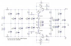
I have made APEX PSU 5 with some modifications (more caps and diferent values). PSU is working fine, but I have problem when positive rail is overloaded with short circuit and fuse is blown. Mpsa42 then gives a smoke in 3 sec. Negative rail is intact.
Input voltage is 2x35vdc, and output is set to 2x25vdc.
And just to add, PSU is amazing... 10mA or 6A load... Output i 24.92-25V constant....
First, I want to know why the mpsa42 dies and what can I do to evercome this problem.
Idea is, that, when positive or negative rail is overloaded, just to blow fuse on rail that has a problem without demage to the parts.
You can see my work:
(There is a bit of more space for first 10000uf cap, i wanted to use wider cap)
Circuit:
PCB
SILK:
SILK+COPPER
Coper was ethched little to much, and the toner has bad quality, so I have added layer of solder
Finish TOP
Finish Side;
Finish Front:
Mounted:
Thank you.
I need help or sugestion for PSU.
I have made APEX PSU 5 with some modifications (more caps and diferent values). PSU is working fine, but I have problem when positive rail is overloaded with short circuit and fuse is blown. Mpsa42 then gives a smoke in 3 sec. Negative rail is intact.
Input voltage is 2x35vdc, and output is set to 2x25vdc.
And just to add, PSU is amazing... 10mA or 6A load... Output i 24.92-25V constant....
First, I want to know why the mpsa42 dies and what can I do to evercome this problem.
Idea is, that, when positive or negative rail is overloaded, just to blow fuse on rail that has a problem without demage to the parts.
You can see my work:
(There is a bit of more space for first 10000uf cap, i wanted to use wider cap)
Circuit:
An externally hosted image should be here but it was not working when we last tested it.
PCB
An externally hosted image should be here but it was not working when we last tested it.
SILK:
An externally hosted image should be here but it was not working when we last tested it.
SILK+COPPER
An externally hosted image should be here but it was not working when we last tested it.
Coper was ethched little to much, and the toner has bad quality, so I have added layer of solder
An externally hosted image should be here but it was not working when we last tested it.
Finish TOP
An externally hosted image should be here but it was not working when we last tested it.
Finish Side;
An externally hosted image should be here but it was not working when we last tested it.
Finish Front:
An externally hosted image should be here but it was not working when we last tested it.
Mounted:
An externally hosted image should be here but it was not working when we last tested it.
Thank you.
I wonder of C7 is back feeding the MPSA when the input collapses to zero volts as the fuse blows?
BTW,
a fuse in the secondary especially before the main smoothing is not a good idea.
You can end up with a railed output offset when one fuse blows and the other remains intact.
And to avoid nuisance blowing during cold start up you need a big fuse, far too big to do anything useful.
Instead use a close rated mains fuse.
A short term severe overload at the PSU output should almost instantly blow a close rated mains fuse.
That will collapse both supply rails.
Hello Andrew,
Thank you for your feedback.
I didn't use C7 and c17. As you sad, firstly I had put 1A fuse in positive rail by mistake, witch blowed right away, and mpsa after that. Last night I shortened output Transistor C-E, and again mpsa42 gives a smoke.
I will follow your advice and place fuse between PSU and Amplifier.
Thank you. If you have other advice, I will be glad to hear.
Best Regards,
Predrag
Don't fuse the Secondaries unless you know the amplifier output will not slew to the other rail.
I am using push switch with ne555 to activate relay for power transformer.
If I want to protect PSU, and amp of bigger damage, can I add monitor circuit for fuses? My idea is to activate push switch circuit when blown fuse is detected so the main teansformer is disconected from power line. Also I want to use same logic for overtemperature situation. For now, I am using DC output protect from aliexpress, and that is only thing that I didn't made myself and it is working fine.
What do you think of overvoltage protection? If one rail fails, I am getting 35v on output. Can I use Overvoltage protection circuit with same logic above? What is the practice?
I have read almost all topics of Mr. Mile APEX diy amp's and tried to implement all those advices.
BR
My Push Switch:
Circuit:
PCB:
PCB+SILK:
SILK:
Circuit:
An externally hosted image should be here but it was not working when we last tested it.
PCB:
An externally hosted image should be here but it was not working when we last tested it.
PCB+SILK:
An externally hosted image should be here but it was not working when we last tested it.
SILK:
An externally hosted image should be here but it was not working when we last tested it.
Also, I am using AC Filter:
An externally hosted image should be here but it was not working when we last tested it.
Fuse monitor circuit:
My idea is something like this...
I am using 12v smps for amplifier standby. Little push On / Push Off circuit board is connected to that 12v supply so as other little toys (fan, dc protect/delay, led's...). As soon as I press Push switch, relay is activated and then the main power transformer is in action feeding my APEX regulated PSU.
When fuses are Ok, relay is not activated. As soon as one rail fuse is blown, that transistor is start to conduct and activates relay, witch then act as push switch, and disconnect main transformer relay.
What do you think about idea and the circuit? Is it silly to build something like this?
Values are a little bit extreme and transistor load is high, but this is fast acting thing, and i think that for a bit of a second that is not a problem... i am not expert to solve that 🙂
Yes, but with both fuses no relais since Q1 pulls as much one side than Q2 to the other.I wish someone can tell me that this idea is stupid and not to do that... Or it is ok...
And there is no garanty that the relais is quicker than the transistor dieing.It isn't you see smoke after 3secs that it has take so long for blowing-up the transistor.
Perhaps better preventing the current gowing the wrong way with a diode (same negative side).
Mona
Attachments
- Status
- Not open for further replies.
- Home
- Amplifiers
- Power Supplies
- Modified APEX Stabilised PSU for ESP p3a-p3b