hello diy'ers. 1st post to this site but been browing for awhile. im a long time mid-fi audio nut & i like to collect & swap around gear & speakers, mainly semi-vintage stuff like mid 80's to late 90's mid-fi stuff, klipsch heritage speakers, adcom, rotel & onkyo components etc etc. i have some basic questions regarding the 555ii adcom amps. i have owned 2 of these amps for 15-25 years, one of them bought new. those 2 have worked great with no issues ever... knock on wood. 😉
but i recently bought a bunch of these 555ii's as part of a klipsch speaker surround system & have some questions about 2 of them & a problem with one of them. i posted the questions/issues over at AK too but found tons of info here after some google searching so figured i'd give diy a try. i will post another thread about the problematic one but my questions for these 2 working amps are as follows:
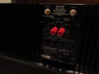
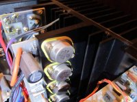
the 2 amps look to have work or upgrades done to them. my main question is regarding the output transistors, does anyone know what adcom originally used in the 555ii? i see red stamped toshibas in my other adcoms which i assume are factory, but these 2 amps have what looks like motorola? "M" mj15025 black stamped & says made in mexico... those 2 amps also have what looks like an upgraded IEC type removeable grounded power cord. but all the others have the original style attached 2 prong cord. does it sound like 2 of these amps may have been worked on/upgraded? are the "M" transistors of decent quality? im sure the factory toshiba transistors are the more desirable ones to have.
also i plan to replace the original electrolytic caps on the ones i keep & need to address possible leaked caps on the 1 that has a issue. will post a new thread for that amp soon.
thanks in advance for any info the adcom gurus can privide.
but i recently bought a bunch of these 555ii's as part of a klipsch speaker surround system & have some questions about 2 of them & a problem with one of them. i posted the questions/issues over at AK too but found tons of info here after some google searching so figured i'd give diy a try. i will post another thread about the problematic one but my questions for these 2 working amps are as follows:
the 2 amps look to have work or upgrades done to them. my main question is regarding the output transistors, does anyone know what adcom originally used in the 555ii? i see red stamped toshibas in my other adcoms which i assume are factory, but these 2 amps have what looks like motorola? "M" mj15025 black stamped & says made in mexico... those 2 amps also have what looks like an upgraded IEC type removeable grounded power cord. but all the others have the original style attached 2 prong cord. does it sound like 2 of these amps may have been worked on/upgraded? are the "M" transistors of decent quality? im sure the factory toshiba transistors are the more desirable ones to have.
also i plan to replace the original electrolytic caps on the ones i keep & need to address possible leaked caps on the 1 that has a issue. will post a new thread for that amp soon.
thanks in advance for any info the adcom gurus can privide.
i can try to get some pics if that will help. but these arent really upgrades, just different transistors & a IEC 3 prong type removeable power cord from what i can see, all caps & other parts look to be factory.
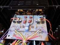
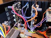
heres a couple pics of one of the amps in question, the other one looks exactly the same. what i notice right away compared to one of the stock looking amps is the insides & pc boards all look much cleaner, almost newer. & all the little resistors with the color stripes on them look newer & are brown on the 2 modded amps, all my other stock amps have blue resistors. also the small 22ohm cement resistors on the amp board look much newer on the modded amps with a slightly different number stamped on it. & the thermal sensors on the heatsinks look new(er) with lots of bright white thermal paste & the wire leads to them look different than a stock one, these have been cut/spliced/heatshrunk on both sets of wires from the sensor & a thinner purple wire is used on one set of wires to the input board, a stock one is only cut/spliced/heatshrunk on one set of wires & they use a little thicker white wire to the board.
aside from that all the other parts inside look the same. the 2 modded amps just seem like someone was inside & cleaned up & replaced some parts & added the grounded power cord... either that or these are much newer amps than the others i own or have seen & adcom changed some things & used different brand parts inside.
any one have any ideas or opinions on what was done. also if you could choose from a stock one vs the modded one with different transistors which would be the keepers? i will do some tests on the bias settings & dc voltage to compare, also may give a listen to help decide which ones to hold onto.
Attachments
anyone have any input on this??
ive been doing some searches here & other places trying to find more info but not much comes up on this topic. the transistors were changed out for one reason or another, im just trying to determine if the replacements are of good/equal quality & meet the same specs as the toshibas, i have read mixed reviews on that, but if they were done right from a competent tech then they should be ok, right?
as for the power cord, ive read that the 3 prong grounded type is better than stock, lots of gear gets upgraded power cords, probably not really needed but nice to have. the other parts i mentioned also look to be newer or slightly different too, any reason why the cement cast & smaller resistors would have all been changed out? sorry for all the questions, just trying to get a better idea of all the changes to these 2 amps.
& i re-checked the dc voltage & bias settings & it seems like the 2 modded amps have a little lower dc voltage than the stock ones, not by much though. all seem to be running at ~1.0, each may flicker to .8-1.4 at random on my cheaper digital multi-meter but being these amps have servo control i think they all should be very close to each other if they are functioning right.
any opinions on keeping the modded/upgraded amps over an original stock one? or on the replacement transistors in general?
Last edited:
Hi adcomman,
Personally, I like to get amplifiers that are original. I'm a technician that used to be authorized warranty for Adcom. Often, people who do a "recap" job aren't trained and have variable soldering skills. It helps immensely if the new parts actually fit properly and are sane values. Massive increases in capacitance is a mark of someone who hasn't a clue about what they are doing.
Check any new amplifiers for output DC offset before connecting speakers of any kind to them. Some Adcom amplifiers were assembled using capacitors that were defective, and these leak their corrosive electrolyte onto the PCB and components. Those boards must be partially depopulated (big job) and inspected carefully. To check for this leakage, use your soldering iron on the board near where the capacitors were. The odor is unmistakable and is the only way to check for this kind of damage. Cleaning the boards and components takes a long time. Be sure to take very clear pictures of the board before you begin any kind of work.
This work is really a job for a good audio technician. DIY is all fine and good, but there are still jobs that do require training and years of experience.
-Chris
thanks for the info anatech. im getting pretty familiar with the leaky caps on the pcb's & will be addressing that asap. i can do basic cap & other pcb component replacement, have above average soldering skills. i do have one defetive 555ii that overheats on the left channel that im trying to diagnose the problem....
but for this post about the 2 amps that look to have been worked on im mainly concerned if the replacement motorola transistors are of good quality & if teh power cord is a worthwhile upgrade to these amps. i plan on keeping a couple amps out of the 5 that i recently purchased & want to keep the "better" ones. seems to me if the work was done well the upgraded amps have newer parts in them & would be the better choice... if the parts are of good quality of course.
the work looks to be done very well, factory looking solder, very clean boards that might have been cleaned before or for whatever reason never had leaky caps. i plan to replace the caps on the input boards asap so i will find out if there is an odor. if the amps work ok & have good dc voltage reading is it safe to assume the caps havent leaked & a replacement will avoid all that hassle?
Hi adcomman,
The mark of a good technician, and something that would allow me to consider buying that amplifier.
New output transistors from On Semi are great. Use them with confidence.
The power cord is a convenience thing. They should be fine.
-Chris
The mark of a good technician, and something that would allow me to consider buying that amplifier.
New output transistors from On Semi are great. Use them with confidence.
The power cord is a convenience thing. They should be fine.
-Chris
Hi adcomman,
The mark of a good technician, and something that would allow me to consider buying that amplifier.
New output transistors from On Semi are great. Use them with confidence.
The power cord is a convenience thing. They should be fine.
-Chris
are the transistors pictured from on semi? they look to be motorola with mj15025 on them. if they are good quality & meet the proper specs i will probably keep these amps since they have been worked on & to me that usually means newer parts that should last longer & that most techs will test other aspects of the amp & replace parts as needed.
i will change out the electrolytic caps & hope for the best. i know the caps on the input board need replaced but do the bigger caps on the output boards need replaced as well? basically all the electrolytics should be swapped out? thanks again.
Motorola sold off/turned into ON Semi around 1999/2000. Same parts different name. Currently it's one of the very few still making the TO-3/TO-204 case style. If the repair was done today those parts would still be viable. They are good parts so don't worry about them.
Craig
Craig
Motorola sold off/turned into ON Semi around 1999/2000. Same parts different name. Currently it's one of the very few still making the TO-3/TO-204 case style. If the repair was done today those parts would still be viable. They are good parts so don't worry about them.
Craig
thanks craig, good to know. sounds like the work was done awhile ago since these are definitely "M" stamped caps not "ON" as they are today.... or they were just an old stock someone had.
if they are considered "good" & are equal or better specs than the original toshibas i will keep these 2 amps since they do look cleaner & possibly had some other parts updated/replaced when the transistors were swapped.
Hi adcomman,
The current On-Semi parts are better still. But the parts you found in there would be what I would use today. Back when that amp was only a few years old, I had access to new real semiconductors from Japan - so I would have used those back then (just to avoid any surprises).
Today, just smile if you need output transistors and buy the current product from On-Semi.
-Chris
Hi adcomman,
The current On-Semi parts are better still. But the parts you found in there would be what I would use today. Back when that amp was only a few years old, I had access to new real semiconductors from Japan - so I would have used those back then (just to avoid any surprises).
Today, just smile if you need output transistors and buy the current product from On-Semi.
-Chris
better by any noticeable amount? the amps sound great & actually in some ways a little better than my original ones....
so original 30-40 year old toshiba parts or 15 year old Motorola parts??... or swap out to brand new ON parts??? hmmm.
probably leave as is.
I know this is an old thread but the amp was not worked on.
The IEC inlet was to allow for easy international sales by using the correct power cord.
The output transistors were changed from the Toshiba's to Motorola in production, they were not replaced. There is a third output transistor option that were the same Motorola parts but private labeled by Motorola.
Hi BTG,
-Chris
That was only a happy byproduct. The CSA test included a drop test. The AC power cord must not fail if the unit is dropped (3' I think) held by a clamped power cord. If the power cord was in a socket, it would bypass this test. Thanks god they picked an already standard power plug and socket! This solved that absolutely stupid CSA requirement. You will note that current light products tend to have AC cords permanently attached like the good old days.The IEC inlet was to allow for easy international sales by using the correct power cord.
-Chris
I know this is an old thread but the amp was not worked on.
The IEC inlet was to allow for easy international sales by using the correct power cord.
The output transistors were changed from the Toshiba's to Motorola in production, they were not replaced. There is a third output transistor option that were the same Motorola parts but private labeled by Motorola.
really? thanks for the info BTG. any idea when the power cord & transistor change happened? i have owned 10+ 555ii's & many other 545ii & 535ii's & all of them had the attached power cord & toshiba transistors, only these 2 i bought recently had the IEC & motorolas.
also these 2 amps have different looking/stamped cement cast resistors on the output boards, & the little resistors on the input & output boards, all other amps have blue ones with red/yellow/orange rings, these 2 have brown ones. i posted some pics earlier if anyone is interested in the differences. just a different supplier i assume.
& can anyone confiirm if there is there a date code in the serial number? would like to know the dates of the amps i have. i am getting ready to
Call Adcom.
just did. they said no info available on supplier or design changes, was too long ago for them to keep the memos. they did say that the IEC plug may have been for amps that could be converted to 220v but didnt have any info on it to say if & when they did that.
as for the "M" stamped transistors & other different parts, no verification of if or when but they said a part could have been discontinued or supply problems etc.
also no date info in the serial numbers so no real way to confirm the age on these. they did say there might have been a small sticker with a date on it but not sure what components would have done that or during what timeframe. just kept saying they are too old to know any of that info... didnt adcom get sold to some other company or person & isnt what it used to be? too bad we dont have anyone that worked for them or had more info on stuff. im into older cars & its great when there is a employee that used to work for GM or ford etc & has first hand knowledge of little things like this.
Adcom is a completely new company. Of course they don`t have any memos. The company was bought and moved to where they are now. Nice people.
The power cords are due to the safety authorities. Plain and simple, that`s why heavy things have them and light things might. The power cord in different markets is a red herring. It was to pass safety certification. Period.
-Chris
The power cords are due to the safety authorities. Plain and simple, that`s why heavy things have them and light things might. The power cord in different markets is a red herring. It was to pass safety certification. Period.
-Chris
- Status
- Not open for further replies.
- Home
- Amplifiers
- Solid State
- adcom gfa 555 ii questions