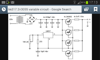

i got all the parts needed and built it . i have had it running but it constantly runs with adjust lm317 and 10k pot not working am i missing somthing simple in this circuit that i just dont understand . could anyone explain the components their size and pins and the gnd points . The transformer i am using puts out 16v ac off load after connecting to my built circuit i get 22v dc at my output and the adjust is not working at all mabe a point of a volt only.

these are the datasheets:
http://www.kynix.com/uploadfiles/pdf86758/2N3055A.pdf
LM317LCPKG3 Datasheet(PDF) - Texas Instruments
I dont see any error in the schematic. The problem must be in the realisation.
10 k is a little too high for 1x V output, but turning it fully down must be enough to reduce output voltage under 1 V.
Try a load! (Eg. 220 ohm 5 W)
10 k is a little too high for 1x V output, but turning it fully down must be enough to reduce output voltage under 1 V.
Try a load! (Eg. 220 ohm 5 W)
I dont see any error in the schematic. The problem must be in the realisation.
10 k is a little too high for 1x V output, but turning it fully down must be enough to reduce output voltage under 1 V.
Try a load! (Eg. 220 ohm 5 W)
You are right. Some loading should bring the output into regulation.
http://www.diyaudio.com/forums/power-supplies/133635-dummy-transformer-question.html
i got all the parts needed and built it . i have had it running but it constantly runs with adjust lm317 and 10k pot not working am i missing somthing simple in this circuit that i just dont understand . could anyone explain the components their size and pins and the gnd points . The transformer i am using puts out 16v ac off load after connecting to my built circuit i get 22v dc at my output and the adjust is not working at all mabe a point of a volt only.
these are the datasheets:
http://www.kynix.com/uploadfiles/pdf86758/2N3055A.pdf
LM317LCPKG3 Datasheet(PDF) - Texas Instruments
Never seen this schematic, but seems totally messed up.
Where does the lm317 get voltage from? lm317 is backwards?
Most of the schematic looks like this. This way you get feedback and don't drift away by heat.
Where does the lm317 get voltage from? lm317 is backwards?
Most of the schematic looks like this. This way you get feedback and don't drift away by heat.
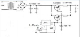
The schematic is legit... but it is messed out in presentation.
Always put V+ / Vin on the left and Vout on the right.
Like this:

Always put V+ / Vin on the left and Vout on the right.
Like this:
Last edited:
Yes, it looks oddNever seen this schematic, but seems totally messed up.
Where does the lm317 get voltage from? lm317 is backwards?
Most of the schematic looks like this. This way you get feedback and don't drift away by heat.

But like this we'r home again 🙄
Mona
Attachments
still, the schematic will not regulate properly...
1) The sensing pin of the 317 in this schematic will never be able to feel the correct output voltage of the circuit. So the output voltage is also influenced by Vbe and the emitter resistance.
2) the current passing through the 3 2n3055 will not be balanced. To achieve this you'll need additional emitter resistors (approx. .22 Ohms). Without these resistors you might expect the 3 transistors to blow-up when the SOA-limits of one of them is exceeded.
I'm actually building my own version of this same power supply for bench usage right now.
This schematic is far better.
Few things missing from your schematic is the kick back protection diodes for the regulator, the fact that 40v is the MAX the LM317 can handle across input to output and should be less than that to be within the safety margin.
Maybe check the adjust pin with a dvm to make sure your potentiometer is varying it. Check the 317 output pin disconnected from the transistors bases to make sure regulated adjustable voltage is coming out. Keep in mind the LM317 tab is also output. You should study the datasheet for it closely.
Finally one must keep in mind that this circuit will produce voltage at high current from the pass transistors but there is no direct short circuit protection so you should fuse the mains input and the final output. Also the emitters of the transistors need current sharing resistors, around 0.1ohm so that small manufacturing differences don't cause one to hog current handling and pop.
edit:
The more I think about this circuit the more I am thinking it wouldn't even regulate voltage. I believe the two transistor version in the Texas Instruments LM317 datasheet would be the better option to go with, or the darlington transistor version shown around the web.
If all you need is a variable unregulated voltage then the previous circuits will work for that.
Last edited:
"If all you need is a variable unregulated voltage then the previous circuits will work for that."
Exactly. These previous versions where the regulators output is connected to the base of the transistor is not a regulated setup.
There is no feedback from the output. There is a schematic in the documentation. Use that.
Exactly. These previous versions where the regulators output is connected to the base of the transistor is not a regulated setup.
There is no feedback from the output. There is a schematic in the documentation. Use that.
Ok. Thank you.😱
Your Schematic has Multiple MAJOR errors. Find another design.
Oh I looked your opinions. And I have tried to find the best schematic. Then I think you are right. Yes, maybe it's too high for the output.🙂
I dont see any error in the schematic. The problem must be in the realisation.
10 k is a little too high for 1x V output, but turning it fully down must be enough to reduce output voltage under 1 V.
Try a load! (Eg. 220 ohm 5 W)
Is that 10uF capacitor meant to be there under pin 2? I've never seen that before. How does the electricity get in /out of the adjustment pin?
- Status
- Not open for further replies.
- Home
- Amplifiers
- Power Supplies
- LM317 & 2N3055 Variable Circuit Problems need help !