Hello,
I have been studying the IRAUDAMP9 documentation and have come upon a detail that I don't understand. In the attached section of the schematic you will see that the IRS2092S Class D driver IC is powered by dedicated +/-5V power supplies VAA and VSS. However, there are also 75k resistors R52 and R50 between B+ and VAA and B- and VSS, respectively. What is the purpose of these resistors? It would seem that they would only serve to inject noise into the power inputs of the IRS2092S.
Thanks for any ideas!
Attachments
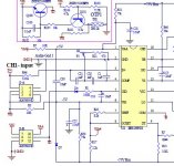
The two 75k resistors inject the power supply to create vaa and vss using the two zener diode presents in Irs2092 package.
If you can see in the iraudamp7d schematics, there are two external zener diode that provide to bypass the internal zener to improve a lower power dissipation of Irs2092.
The concept assumed in the iraudamp7d is equal to iraudamp9 without the external zener.
In the iraudamp9 two 75 k resistors are used to pull down the high power dissipation of the internal zener, so, of the entire Irs2092 package, expecially if you use an Smd version.
So, the two 10ohm resistor connected directly to vaa and vss are used to supply other circuit parts that require this voltages.
Regards.
As Mario says there are two internal zeners. These work in conjunction with external resistors to the power supplies.
I have seen various ways of implementing the VAA and VSS supplies.
Just resistors, external zeners and external voltage regulators.
I have seen various ways of implementing the VAA and VSS supplies.
Just resistors, external zeners and external voltage regulators.
Thank you both for your responses, but I don't think you are correct. If you look at the complete IRAUDAMP9 PDF you will see that there are dedicated switching regulators that supply Vss and Vaa. The 75k resistors would also be too high a value for use as droppers from the high voltage rails in the manner used in the IRAUDAMP7 schematic. Still curious what the need is for these resistors.
Thank If you look at the complete IRAUDAMP9 PDF you will see that there are dedicated switching regulators that supply Vss and Vaa.
That is one of the options I gave.
I have made a few irs2092 based systems and always used the resistor and internal diodes and not had any problems.
If you use external regs or SMPS then the resistors are redundant.
Thank you both for your responses, but I don't think you are correct. If you look at the complete IRAUDAMP9 PDF you will see that there are dedicated switching regulators that supply Vss and Vaa. The 75k resistors would also be too high a value for use as droppers from the high voltage rails in the manner used in the IRAUDAMP7 schematic. Still curious what the need is for these resistors.
Watching carefully the IRAUDAMP9 document, you're right!
I saw wrong.
In this case, I think the two 75k resistors may have the bootstrap function at startup, providing a minimum starting voltage, which then rises gradually until you get to +/- 5V (see the start-up scheme and off), but mine is just a guess.
Just to close off this discussion: I contacted Infineon (IR) technical support and they confirmed that there is an error both in the main schematic and the BOM. You can use EITHER +/- 75V derived supplies with the 75k resistors, or the external +/- 5V regulators with the 10R resistors, not both. Mystery solved.
- Status
- Not open for further replies.
- Home
- Amplifiers
- Class D
- Question about IRAUDAMP9 schematic