I've got four 5" woofers that were salvaged from a pair of ProAudio Stage 5.1:

One of the tweeters are broken, so I'm hoping I could combine the woofers with a pair of Vifa BC25SC55 I have laying around.
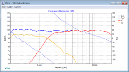
I put one of each in a test baffle and measured the response at 0, 15 and 30 deg at 1 m distance (~2 m above ground):
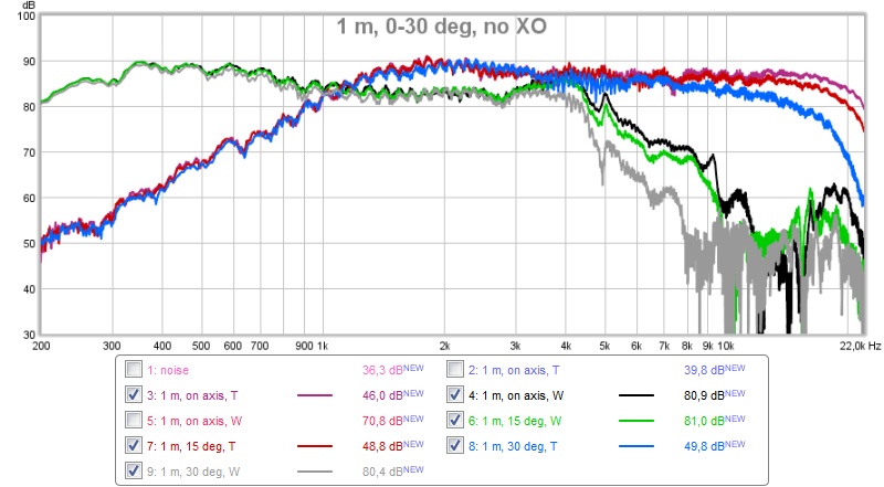
The woofer level was set to 6 dB above tweeter level (using miniDSP) to emulate having two woofers.
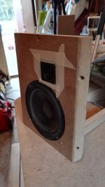
The woofer is not in an enclosure, but only on a baffle with a lot of stuffing behind (not shown):

That's the reason for the early fall off and slight dipole bump. I've measured the woofer earlier in a closed box and gotten a fairly flat response without any XO (or BSC).
I've measured the impedance of the woofers in free air and traced the impedance of the tweeter in the datasheet, all attached with exported FRD-files from the first figure (on axis).
The tweeter needs 34 mm delay (0.1 ms) for the impulses to coincide. This is a number that can be modified by making a stepped baffle or rear-mounting the woofers. I prefer to do the latter, i.e. a ~45 ms difference.
Now to my questions...
1. Are the FRD-files correctly exported from REW? Do I need to do anything with the data before I export it to XSim?
2. I'm novice at designing filters, how do I build the cheapest possible filter for this set?
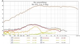
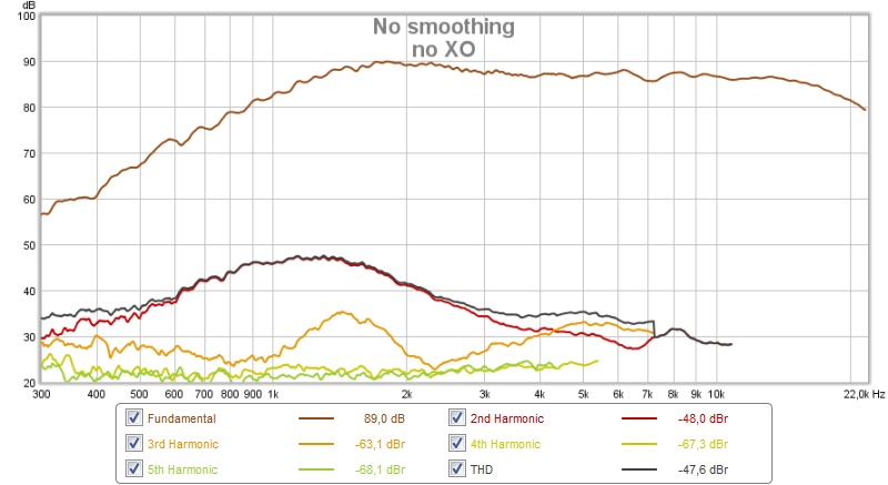
3. With #2 in mind, is it possible to run the tweeter without an XO? My first thought was that it's impossible (would damage tweeter), but I tried running distortion sweeps and got this at ~89 dB:
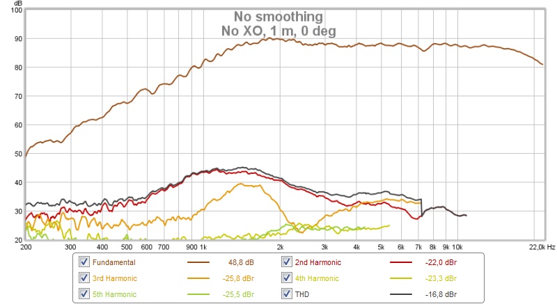
The tweeter resonance at 1.3 kHz makes the XO a little difficult/expensive.
/Anton
One of the tweeters are broken, so I'm hoping I could combine the woofers with a pair of Vifa BC25SC55 I have laying around.
I put one of each in a test baffle and measured the response at 0, 15 and 30 deg at 1 m distance (~2 m above ground):
The woofer level was set to 6 dB above tweeter level (using miniDSP) to emulate having two woofers.
The woofer is not in an enclosure, but only on a baffle with a lot of stuffing behind (not shown):
That's the reason for the early fall off and slight dipole bump. I've measured the woofer earlier in a closed box and gotten a fairly flat response without any XO (or BSC).
I've measured the impedance of the woofers in free air and traced the impedance of the tweeter in the datasheet, all attached with exported FRD-files from the first figure (on axis).
The tweeter needs 34 mm delay (0.1 ms) for the impulses to coincide. This is a number that can be modified by making a stepped baffle or rear-mounting the woofers. I prefer to do the latter, i.e. a ~45 ms difference.
Now to my questions...
1. Are the FRD-files correctly exported from REW? Do I need to do anything with the data before I export it to XSim?
2. I'm novice at designing filters, how do I build the cheapest possible filter for this set?
3. With #2 in mind, is it possible to run the tweeter without an XO? My first thought was that it's impossible (would damage tweeter), but I tried running distortion sweeps and got this at ~89 dB:
The tweeter resonance at 1.3 kHz makes the XO a little difficult/expensive.
/Anton
Attachments
No. You'll destroy the tweeter in an heartbeat with normal music. A tweeter doesn't have surface and xmax to sustain a bass note.is it possible to run the tweeter without an XO?
Ralf
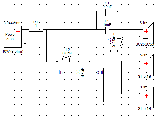
First attempt at making cheap XO
Ralf: That's what I thought. Got a little confused with the distortion measurements.
I've experimented a little in XSim and arrived at this:
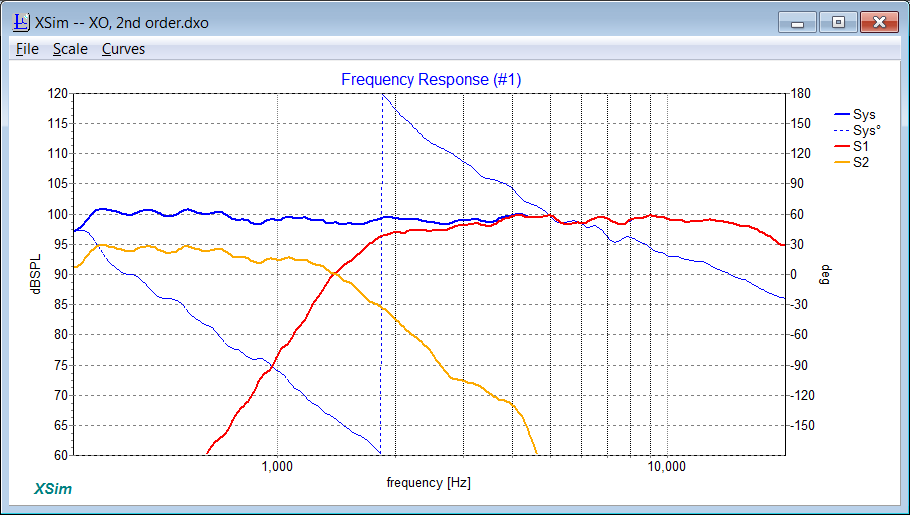
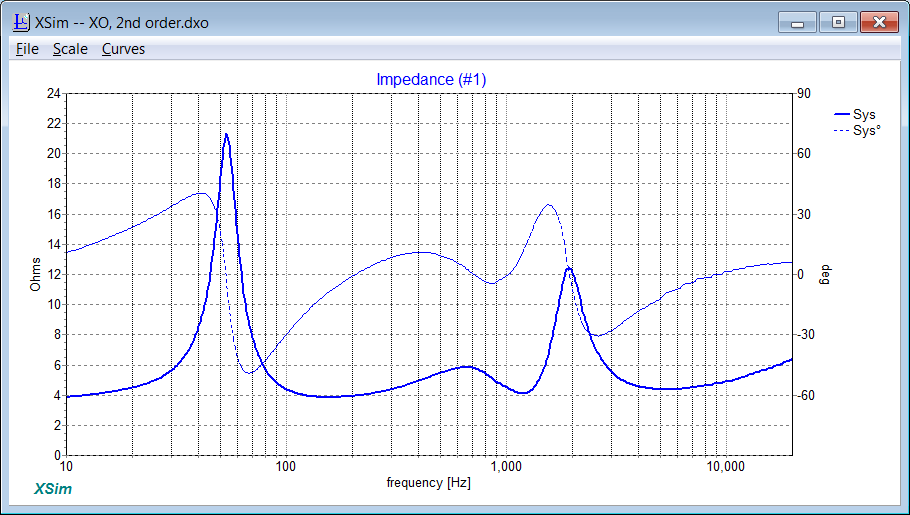
I already have 10 and 2.2 uF capacitors. The 47 uF is a electrolytic (ok for woofer bypass I hope) and the 0.6 and 0.25 mH coils are fairly cheap if 20 AWG. The resistor is a 10 W ceramic to raise the impedance above 4 Ohm. Necessary? I don't know, but easy and cheap.
I also used REW to calculate Thiele-Small paramters. This is the result:
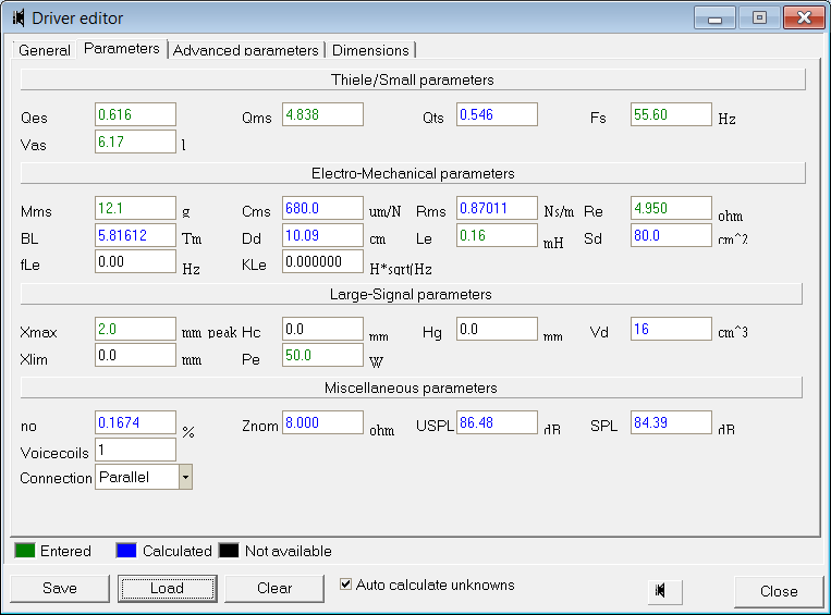
If I run that in WinISD i get that a 30 l box tuned to 42 Hz gives a flat response with -3 dB at 36 Hz. I'll probably try a MLTL as I'm aiming for a 120 cm tall tower speaker.
/Anton
Ralf: That's what I thought. Got a little confused with the distortion measurements.
I've experimented a little in XSim and arrived at this:
I already have 10 and 2.2 uF capacitors. The 47 uF is a electrolytic (ok for woofer bypass I hope) and the 0.6 and 0.25 mH coils are fairly cheap if 20 AWG. The resistor is a 10 W ceramic to raise the impedance above 4 Ohm. Necessary? I don't know, but easy and cheap.
I also used REW to calculate Thiele-Small paramters. This is the result:
If I run that in WinISD i get that a 30 l box tuned to 42 Hz gives a flat response with -3 dB at 36 Hz. I'll probably try a MLTL as I'm aiming for a 120 cm tall tower speaker.
/Anton
Attachments


What are the crossover frequency? It should be close to 3.000 Hz! Yours seem to be below 2.000 Hz. Your tweeter will not have much powehandling that low, unless you have a very steep filter.
I don't know how reliable are your measurements. See here for a well written white paper: http://audio.claub.net/software/FRD_Blender/White%20Paper%20-%20Accurate%20In-Room%20Frequency%20Response%20to%2010Hz.pdf
Please note at least three points: far field gated measure (for both drivers), near field measure for the woofer, minimum phase calculation. Without blending near and far field woofer measures you can't judge the baffle step effect, if not gated the measures contain also the room effect, without the correct phase the crossover won't work as expected.
As for the crossover you've shown, the only real wrong thing is a resistor in series with the woofer: it can get very hot or even burn, and lowers the woofer SPL. How are now wired the two woofers in the ProAudio speaker, in series or parallel? If in parallel it is safe to assume they are a "normal" load for an amp. For a health check measure the DC resistance with a multimeter.
Ralf
Don't forget to put in XSim a correct ESR value for the coils you intend to buy.
Edit 1: Agreed with Kjelden on the XO point, 2.5KHz is IMHO the lowest frequency for this tweeter with a LR4 acoustic slope.
Edit 2: You have to measure on the baffle you intend to use in the final build.
Last edited:
What are the crossover frequency? It should be close to 3.000 Hz! Yours seem to be below 2.000 Hz. Your tweeter will not have much powehandling that low, unless you have a very steep filter.
Thanks for the link, I'll look more closely on the document later.I don't know how reliable are your measurements. See here for a well written white paper: http://audio.claub.net/software/FRD_Blender/White%20Paper%20-%20Accurate%20In-Room%20Frequency%20Response%20to%2010Hz.pdf
Please note at least three points: far field gated measure (for both drivers), near field measure for the woofer, minimum phase calculation. Without blending near and far field woofer measures you can't judge the baffle step effect, if not gated the measures contain also the room effect, without the correct phase the crossover won't work as expected.
As for the crossover you've shown, the only real wrong thing is a resistor in series with the woofer: it can get very hot or even burn, and lowers the woofer SPL. How are now wired the two woofers in the ProAudio speaker, in series or parallel? If in parallel it is safe to assume they are a "normal" load for an amp. For a health check measure the DC resistance with a multimeter.
Ralf
Don't forget to put in XSim a correct ESR value for the coils you intend to buy.
Edit 1: Agreed with Kjelden on the XO point, 2.5KHz is IMHO the lowest frequency for this tweeter with a LR4 acoustic slope.
Edit 2: You have to measure on the baffle you intend to use in the final build.
I haven't really defined what the goal is, I hope that answers some questions:
The speakers will be used (by my brother in law) at a distance of about 1.5 m in a small room (10 m^2/108 ft^2). The amp will be a TPA3116 with 19 V PSU, so a maximum of about 20 W/channel.
The short listening distance causes me to aim for a low XO to avoid directivity issues.
Of course I'll need to build the real enclosure, I just felt like getting some input on the XO (my weakest area) to know whether the project is feasible or not.
The datasheet (here) says that the tweeter can take 100 W between above 1.4 kHz. Or am I interpreting that incorrectly?
Oh, and the measurements are done outdoor at 1 m, 2 m above ground. At least 6 m to closest wall.
/Anton
If I wasn't very clear: Cost is a large factor in this build. I'm hoping to build these for a cost of less than $100 as all parts so far were free and my brother in law isn't that picky with sound. He lives with his parents, so he doesn't need any 100 dB+ speakers. Just for music and movies in his room.
You should be able to cross at 2600 Hz to a 5" without any directivity issues.
Rule of thumb formual 13.740/5" = 2.748 Hz
Rule of thumb formual 13.740/5" = 2.748 Hz
You still have to gate, as your environment is not an anechoic chamber. Measurement point at 1m, with the closest boundary at 2m, lead to a gate at 110Hz. You have ripples in your measures than can be related to that.the measurements are done outdoor at 1 m, 2 m above ground. At least 6 m to closest wall.
You don't have to build the real enclosure yet, just build the baffle you intend to use and make a fully stuffed cardboard enclosure, to eliminate the dipole effect. Or build a sort of infinite baffle, and simulate the effect of whatever baffle you want to use.Of course I'll need to build the real enclosure, I just felt like getting some input on the XO (my weakest area) to know whether the project is feasible or not.
There is more than a simple harmonic distortion in the overall performance. And there is also long term physical stress. If not proven otherwise, I wouldn't cross a tweeter lower than 2x the resonant frequency, better with a LR4 acoustic slope.The datasheet (here) says that the tweeter can take 100 W between above 1.4 kHz. Or am I interpreting that incorrectly?
I see your test baffle with one woofer only, but I gather you intend to use 2 woofers with one tweeter per enclosure. This pose a dilemma for the drivers arrangement. If you opt for a 2 way design you have to build a WTW and not a TWW, otherwise the lower woofer is too far from the tweeter at the crossover point for a proper sound integration. If you want to build a 2.5 way speaker, a TWW arrangement is fine.
Ralf
Measurement of tweeter with 2nd order XO at 1.7 kHz
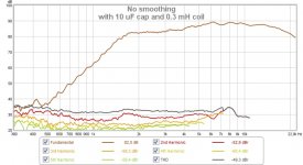
I found components in my workshop for a ~1.7 kHz XO (close to filter in post 3), a 10 uF capacitor and a 0.3 mH coil.
Here's a comparison of
- blue: no filter
- red: with 10 uF cap
- grey: with 10 uF cap and 0.3 mH coil
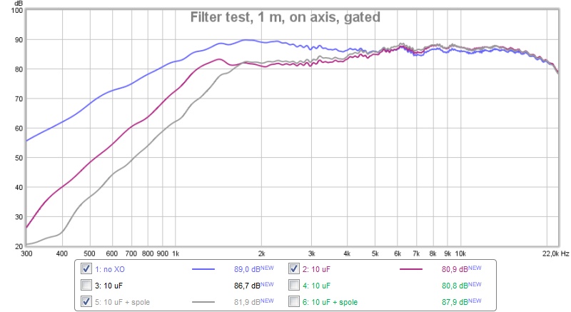
Distortion for the three measurements:
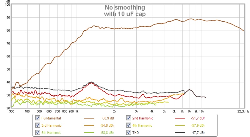
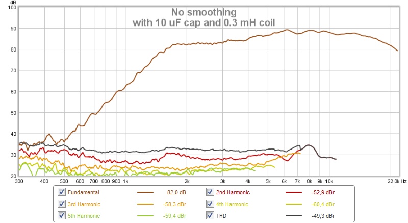
Sure, the frequency response is a little odd and requires an interesting shape from the woofers, but I don't see why I the tweeter would need a higher XO than this (at least at moderate levels). Please enlighten me 🙂
/Anton
I found components in my workshop for a ~1.7 kHz XO (close to filter in post 3), a 10 uF capacitor and a 0.3 mH coil.
Here's a comparison of
- blue: no filter
- red: with 10 uF cap
- grey: with 10 uF cap and 0.3 mH coil
Distortion for the three measurements:
Sure, the frequency response is a little odd and requires an interesting shape from the woofers, but I don't see why I the tweeter would need a higher XO than this (at least at moderate levels). Please enlighten me 🙂
/Anton
Attachments

Alright 🙂You should be able to cross at 2600 Hz to a 5" without any directivity issues.
Rule of thumb formual 13.740/5" = 2.748 Hz
I'm guessing there is some kind of dependence on distance to speaker as well. If you are infinitely far away the CTC should be unimportant, but very close more important, no?
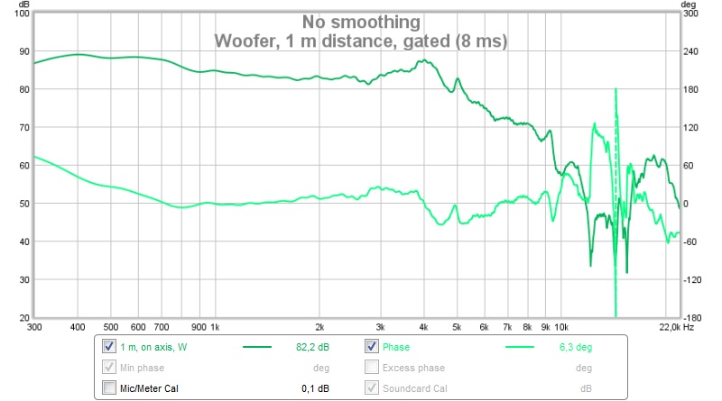
Sure, I'll gate. My last post was gated at 8 ms (just before ground reflection).You still have to gate, as your environment is not an anechoic chamber. Measurement point at 1m, with the closest boundary at 2m, lead to a gate at 110Hz. You have ripples in your measures than can be related to that.
You don't have to build the real enclosure yet, just build the baffle you intend to use and make a fully stuffed cardboard enclosure, to eliminate the dipole effect. Or build a sort of infinite baffle, and simulate the effect of whatever baffle you want to use.
There is more than a simple harmonic distortion in the overall performance. And there is also long term physical stress. If not proven otherwise, I wouldn't cross a tweeter lower than 2x the resonant frequency, better with a LR4 acoustic slope.
I see your test baffle with one woofer only, but I gather you intend to use 2 woofers with one tweeter per enclosure. This pose a dilemma for the drivers arrangement. If you opt for a 2 way design you have to build a WTW and not a TWW, otherwise the lower woofer is too far from the tweeter at the crossover point for a proper sound integration. If you want to build a 2.5 way speaker, a TWW arrangement is fine.
Ralf
I'm sure LR4 is nice, but that's a lot of components. I'm hoping we can work some magic and get something that sounds nice without textbook filters and expensive components.
I'm indeed planning a WTW configuration, with a slightly offset tweeter (as in the test baffle) to reduce effects from diffraction. I'll build an simple enclosure with correct baffle. I do feel that I need to experiment with the mounting of the woofers (front or rear mount).
Thanks for all the guidance! I've been focusing way too much lately building crazy prototypes (synergies, leaky cardiods etc.) and felt that it would be nice to build a classic speaker with ordinary XOs (instead of DSP).
If the resistor is a bad idea, is it okay to let the impedance sink to 3 Ohm? How will the amplifier react?
/Anton
How much power is going to the tweeter in your distortion tests?
Edit - if you make distortion measures at normal to high SPL, and distortion is low. Then, just go for it.
Edit - if you make distortion measures at normal to high SPL, and distortion is low. Then, just go for it.
Last edited:
Are you saying that combining the woofers I have with that tweeter is a bad idea?I suggest you cross this tweeter at 3,000Hz to 3,500Hz (12dB/oct).
This is the woofer response:
That can't be crossed between 3 and 3.5 kHz...
Well, the level is the same as Vifas measurement for sensitivity (89.6 dB/W), so it should be ~1 W. I almost never play above 90 dB in my living room, only to test equipment. So I don't think these speakers will be pushed much above that.How much power is going to the tweeter in your distortion tests?
Why?
/Anton
Attachments

Are you saying that combining the woofers I have with that tweeter is a bad idea?
/Anton
No. What I'm saying is this tweeter is more comfortable at the frq I suggested. Bearing in mind the fs is 1,400Hz, I would cross not lower than 2,800Hz.
That can't be crossed between 3 and 3.5 kHz...
It should not be a problem with a 5" woofer. All you have to do is to take care of the cone breakup. If you don't want to do that, go for a Seas 27TBFC or something similar. You'll be able to cross easily at 2,200Hz.
Last edited:
You didn't fully read what I wrote. Acoustic slope is not equal to electrical slope. The acoustic slope is what matters, and is quite easy to reach LR4 slopes with less than 4th order electrical slopes. Accounting for the different depth of the drivers, a good slightly asymmetrical LR4 crossover (that shows a deep reverse null), can be obtained with a 2nd order electrical on the woofer and 3rd order electrical on the tweeter.I'm sure LR4 is nice, but that's a lot of components.
I suggest you to try to design a 2.5KHz or slightly higher crossover, and don't forget that components for a higher crossover point are cheaper (lower values).
Ralf
If you have miniDSP, are you planning on making it active? If so that will work without a passive crossover. You'll just put the crossover in miniDSP instead.
Otherwise, of coures, you need a crossover. Most tweeter specs include a minimum required crossover.
So if you are doing active, make sure you measure the tweeter to woofer distance before going nuts in XSim.
Best,
Erik
Otherwise, of coures, you need a crossover. Most tweeter specs include a minimum required crossover.
So if you are doing active, make sure you measure the tweeter to woofer distance before going nuts in XSim.
Best,
Erik
I've got four 5" woofers that were salvaged from a pair of ProAudio Stage 5.1:
One of the tweeters are broken, so I'm hoping I could combine the woofers with a pair of Vifa BC25SC55 I have laying around.
I put one of each in a test baffle and measured the response at 0, 15 and 30 deg at 1 m distance (~2 m above ground):
The woofer level was set to 6 dB above tweeter level (using miniDSP) to emulate having two woofers.
The woofer is not in an enclosure, but only on a baffle with a lot of stuffing behind (not shown):
That's the reason for the early fall off and slight dipole bump. I've measured the woofer earlier in a closed box and gotten a fairly flat response without any XO (or BSC).
I've measured the impedance of the woofers in free air and traced the impedance of the tweeter in the datasheet, all attached with exported FRD-files from the first figure (on axis).
The tweeter needs 34 mm delay (0.1 ms) for the impulses to coincide. This is a number that can be modified by making a stepped baffle or rear-mounting the woofers. I prefer to do the latter, i.e. a ~45 ms difference.
Now to my questions...
1. Are the FRD-files correctly exported from REW? Do I need to do anything with the data before I export it to XSim?
2. I'm novice at designing filters, how do I build the cheapest possible filter for this set?
3. With #2 in mind, is it possible to run the tweeter without an XO? My first thought was that it's impossible (would damage tweeter), but I tried running distortion sweeps and got this at ~89 dB:
The tweeter resonance at 1.3 kHz makes the XO a little difficult/expensive.
/Anton
Right, thanks for pointing that out. Can you do a simple example with the files I have?You didn't fully read what I wrote. Acoustic slope is not equal to electrical slope. The acoustic slope is what matters, and is quite easy to reach LR4 slopes with less than 4th order electrical slopes. Accounting for the different depth of the drivers, a good slightly asymmetrical LR4 crossover (that shows a deep reverse null), can be obtained with a 2nd order electrical on the woofer and 3rd order electrical on the tweeter.
I suggest you to try to design a 2.5KHz or slightly higher crossover, and don't forget that components for a higher crossover point are cheaper (lower values).
Ralf
Especially expensive is the high value caps for the tweeter as they can't be electrolytic. Is it a correct observation that electrolytic caps are fine for woofer bypass but should be avoided in series with the tweeter?
Well, I already own the Vifa BC25SC55-04 and hope to build a decent speaker with it. I'm aware that it won't be amazing, but it will be almost free, so why not make it if it is possible to get decent sound to someone who doesn't own any speakers.No. What I'm saying is this tweeter is more comfortable at the frq I suggested. Bearing in mind the fs is 1,400Hz, I would cross not lower than 2,800Hz.
It should not be a problem with a 5" woofer. All you have to do is to take care of the cone breakup. If you don't want to do that, go for a Seas 27TBFC or something similar. You'll be able to cross easily at 2,200Hz.
I'm only using the miniDSP during measurements. Vifa (or Tymphany) doesn't seem to specify any minimum crossover (or order).If you have miniDSP, are you planning on making it active? If so that will work without a passive crossover. You'll just put the crossover in miniDSP instead.
Otherwise, of coures, you need a crossover. Most tweeter specs include a minimum required crossover.
So if you are doing active, make sure you measure the tweeter to woofer distance before going nuts in XSim.
Best,
Erik
/Anton
Sorry don't have the time now, but you can have a look here for an example:Right, thanks for pointing that out. Can you do a simple example with the files I have?
Zaph|Audio - ZA-SR71
PCD is a better app when it comes to compare the crossover induced slope with a target slope.
A question about caps can start a war. IMHO electrolytic caps are fine everywhere, but they degrade over time, and for this reason only I chose to use film caps even in the woofer part. The other important difference between electrolytic and film caps is in the ESR, much lower for film ones.Especially expensive is the high value caps for the tweeter as they can't be electrolytic. Is it a correct observation that electrolytic caps are fine for woofer bypass but should be avoided in series with the tweeter?
Ralf
Alright, thanks! Then I'll go for electrolytics for woofer bypass at least. The woofers are at least 10 years old and have foam surrounds. If the speaker survives another 15 years I'm satisfied.Sorry don't have the time now, but you can have a look here for an example:
Zaph|Audio - ZA-SR71
PCD is a better app when it comes to compare the crossover induced slope with a target slope.
A question about caps can start a war. IMHO electrolytic caps are fine everywhere, but they degrade over time, and for this reason only I chose to use film caps even in the woofer part. The other important difference between electrolytic and film caps is in the ESR, much lower for film ones.
Ralf
I'll try PCD.
/Anton
- Status
- Not open for further replies.
- Home
- Loudspeakers
- Multi-Way
- Tweeter without high pass? Help with XO!