Andrew T has always been very helpful to all of us on a variety of subjects. A second look by a critical eye can save a lot of headaches before the PCB is etched and the "concrete has been poured" - he had some great suggestions that has improved the CFH7 amp here. I wish he would make one so we can get his listening impressions.
Thanks Andrew T.
Thanks Andrew T.
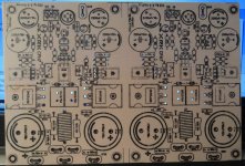
A start.
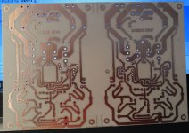
I find it amazing how you are able to get such good results with iron transfer, both with silk and copper. especially some of the traces here are too close to comfortably transfer. You, the expert
 .
.You have it explained somewhere here, I tried it, failed miserably and then tried photo-resist, with a success rate of about 50%😱 I think it needs, lots and lots of transfers to get real good at it for the "unskilled" like me.
I find it amazing how you are able to get such good results with iron transfer, both with silk and copper. especially some of the traces here are too close to comfortably transfer. You, the expert
You have it explained somewhere here, I tried it, failed miserably and then tried photo-resist, with a success rate of about 50%😱 I think it needs, lots and lots of transfers to get real good at it for the "unskilled" like me.
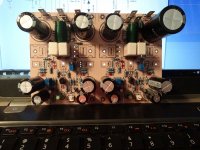
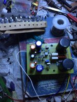
It takes some practice but I get my boards for about $1 each and it adds to the enjoyment. It also means I can build and test an amp in a day or two if I have all the parts on hand. This one is populated aside from the transistors that mount on the heatsink. I have to round one up. Maybe tomorrow.
I you look at the pic you will see red marks where I have used SMD parts under the board.
Blessings, Terry
Attachments
Terry,
Nice looking board(s) there - can you show us the other side with the SMT caps? Good luck on first sound.
Nice looking board(s) there - can you show us the other side with the SMT caps? Good luck on first sound.
Terry,
Nice looking board(s) there - can you show us the other side with the SMT caps? Good luck on first sound.
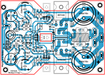
Sure
Attachments
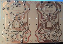
That looks really neat. Maybe we should always put little pads for the typical 100nF bypass caps that are so common in all our layouts in the future? I have a big roll of those x7r caps. I see you are using nice c0g/np0 for the 10pF's. But placing them right at pins of the drivers is probably one of the best ways to keep stray capacitance down.
Thanks for sharing the undersides - not a view we often get to see on most amps.
Thanks for sharing the undersides - not a view we often get to see on most amps.
Last edited:
Hello
greetings please check biasing circuit R15 6K8 on schematic from base to collector
of BD 139 on pcb 6k8 is from base to emitter second 1UF on schematic from
collector to emitter on pcb 1uf is from collector in series through 6K8 resistor to
base of BD 139
warm regards
Andrew
greetings please check biasing circuit R15 6K8 on schematic from base to collector
of BD 139 on pcb 6k8 is from base to emitter second 1UF on schematic from
collector to emitter on pcb 1uf is from collector in series through 6K8 resistor to
base of BD 139
warm regards
Andrew
Well, I will just have to cut traces and install jumpers at this time. Too much work done to just start over.
We are all on the edge of our seats. 🙂
Thanks to all for the layouts and quick builds. This has been a great rapid collaboration. My boards should be waiting in the mail for me when I get back. I have the gen1 Idefixes boards. Hopefully there's no Vbe multiplier mixup on that one.
Thanks to all for the layouts and quick builds. This has been a great rapid collaboration. My boards should be waiting in the mail for me when I get back. I have the gen1 Idefixes boards. Hopefully there's no Vbe multiplier mixup on that one.
We are all on the edge of our seats. 🙂
Thanks to all for the layouts and quick builds. This has been a great rapid collaboration. My boards should be waiting in the mail for me when I get back. I have the gen1 Idefixes boards. Hopefully there's no Vbe multiplier mixup on that one.
As in diptrace schematic and layout are related there should be no difference between them.
Marc
Were the gate stoppers not pretty low in value, and no gate zobel either? Might be worth popping in bigger gate stoppers, say at least 100R.
- Home
- Amplifiers
- Solid State
- CFH7 Amp