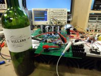
I was inspired by the image of Nelson's "randomly attached parts" in post #189 http://www.diyaudio.com/forums/pass-labs/267857-aleph-design-reloaded-19.html#post4786083, and his later comment http://www.diyaudio.com/forums/pass-labs/267857-aleph-design-reloaded-22.html#post4790203 "You guys are sooo entertaining. I think I'll regularly post a picture of parts randomly attached on my bench and let you go at it."
Attachments
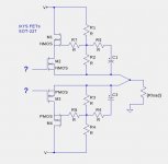
Having studied that parts and wiring that was visible in the image, I came up with a guess that the output stage is a cascoded source follower, shown below. Althouygh it was not possible to see enough details of the front-end which drives the gates of the output fets, it appears to be based on part of a Pass-Labs front-end board from some series of amplifiers, perhaps a single-channel XA.8.
Attachments
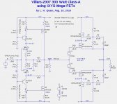
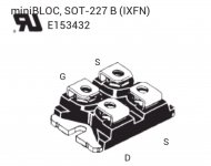
Accepting Nelson's challenge, I took a stab at designing a Class-A amplifier using IXYS Mega-FETs. Studying the IXYS FET datasheets, particurly those in SOT-227 (MiniBLOC) packages, I chose the IXTN120P20T and IXTN110N20L2 200V FETs. These huge FETs have very high capacitances, which motivates the use of cascoding.
P-Spice models are available at P-Spice Model. I have no idea how well the Spice models predict device the behavior at under the conditions of my design.
Shown below is the LTSpice schematic for my design, which has the following specs:
The resistor values need to be tweaked to get to the nearest standard 1% values. To really implement my design will require acquiring some of these IXYS FETs and making measurements at the design voltages and currents.
P-Spice models are available at P-Spice Model. I have no idea how well the Spice models predict device the behavior at under the conditions of my design.
Shown below is the LTSpice schematic for my design, which has the following specs:
- RMS output into 8 Ohms: 300 Watts
- Closed-Loop Gain: 20X (26dB)
- Front-End Open-Loop Gain: 38dB
- No global negative feedback
- Idle Power Dissipation: 360 Watts
The resistor values need to be tweaked to get to the nearest standard 1% values. To really implement my design will require acquiring some of these IXYS FETs and making measurements at the design voltages and currents.
Attachments
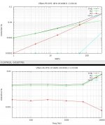
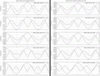
Somewhat disturbing is the AC response of the cascoded output stage above about 100kHz. The non-cascoded version of the output stage does not show this behavior, but have much higher distortion due to the high capacitances.
Attachments

Remarkably, while your schematic has different values in various places,
it gets similar numbers and shows some of the same effects (flaws).
I was exploring was the ability of cascoding to improve the Gate-Drain
capacitive nonlinearity of the hockey pucks. In this case it was not particularly
good. I will add that there are no additional plans for this circuit approach at
this time...
😎
Nelson: I am a bit surprised that the IXYS Spice models were good enough to produce similar results. I thought the 3rd harmonic (H3) behavior in the simulation was overly optimistic, perhaps due to the internal source resistance being too small and the simulated device being close to the ideal square-law behavior. But if your measurements also showed such low H3 then maybe the models aren't too bad.
Nelson: Were you able to maintain stable bias currents vs. temperature in your tests without using source resistors on the IXYS FETs? The datasheets suggest an unfavorable temperature coefficient.
I was inspired by the image of Nelson's "randomly attached parts" in post #189 http://www.diyaudio.com/forums/pass-labs/267857-aleph-design-reloaded-19.html#post4786083, and his later comment http://www.diyaudio.com/forums/pass-labs/267857-aleph-design-reloaded-22.html#post4790203 "You guys are sooo entertaining. I think I'll regularly post a picture of parts randomly attached on my bench and let you go at it."
Great lhquam!
and you were right no Aleph but cascaded source follower.
Nevetheless I will try an Aleph3 clone with the IXFN120N20P with only 6nF Ciss.
Aleph back to the future trip is really nice…..
🙂
Nelson: I am a bit surprised that the IXYS Spice models were good enough to produce similar results.
I took another look at it, and realized that they looked the same from a
curve shape, but were offset quite a bit. The simulations were pretty optimistic,
particularly as I allowed more DC voltage on the output devices,
which minimizes the capacitive effects.
This speaks to our discussion about adjusting models to fit actual results.
😎
Nelson: Were you able to maintain stable bias currents vs. temperature in your tests without using source resistors on the IXYS FETs? The datasheets suggest an unfavorable temperature coefficient.
I keep one finger on the bias pot at all times. 😀
Actually, use enough heat sinking and it's not such a problem.
😎
Remarkably, while your schematic has different values in various places,
it gets similar numbers and shows some of the same effects (flaws).
I was exploring was the ability of cascoding to improve the Gate-Drain
capacitive nonlinearity of the hockey pucks. In this case it was not particularly
good. I will add that there are no additional plans for this circuit approach at
this time...
😎
I found this old thread titled "Baxandall Super Pair" http://www.diyaudio.com/forums/solid-state/25172-baxandall-super-pair.html that discusses topologies similar to and including the Hawksford Cascode and their tendency to overshoot and possibly oscillate.
It seems that every time you push on a flaw, something else bulges out.
It comes down to reasonable compromises.
😎
It comes down to reasonable compromises.
😎
- Status
- Not open for further replies.
- Home
- Amplifiers
- Pass Labs
- Villars 2007 Power Amplifier