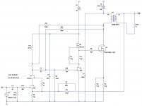
I'll look tonight if I remember for the value of the feedback resistor omitted in the original schematic. A hint - it was considerably in excess of 10k - more like in the region of 330k.
What is the impedance of the transformer you used in your simulation? I used the One Electron UBT-1 in the actual amplifier, which has a 1.6k primary impedance (14.1:1 turns ratio). A higher impedance transformer will have a larger step-down ratio, lowering the loop gain and increasing THD, also reducing the available output power.
What is the impedance of the transformer you used in your simulation? I used the One Electron UBT-1 in the actual amplifier, which has a 1.6k primary impedance (14.1:1 turns ratio). A higher impedance transformer will have a larger step-down ratio, lowering the loop gain and increasing THD, also reducing the available output power.
With a proper SPICE model for the UBT-1, a good value for R13 seems to be 120k. Output power is now 7.5W into 8 ohm at 1kHz with 1.7% THD. Efficiency seems to be less than 10%, but such is the nature of these beasts. 😉
Attachments
Last edited:
Look at it this way, at least you're not in the ridiculous situation of burning more power in the tube filaments than you deliver to the load...
Edit - On another note, it's interesting that you cite 120k as a good value for the partial feedback resistor. I would have used a higher value so as to leave some gain for the global feedback loop. That extra gain also helps to straighten out the output transformer - this shows up in the square wave response. For an example, check out the "SiC Puppy" thread where I show the square wave response of that amplifier (also using UBT-1 transformers) before and after closing the global loop.
Edit - On another note, it's interesting that you cite 120k as a good value for the partial feedback resistor. I would have used a higher value so as to leave some gain for the global feedback loop. That extra gain also helps to straighten out the output transformer - this shows up in the square wave response. For an example, check out the "SiC Puppy" thread where I show the square wave response of that amplifier (also using UBT-1 transformers) before and after closing the global loop.
Last edited:
Has anyone tried a lower voltage Schade Semisouth 085? Search turned up this thread. I don't know about using 300v. Rather not.
I want to keep it simple like the SIT-1 monos. 😉
Don't mind using high power resistors for the current source.
10w sounds nice. 🙂
I was going to try to combine the Nemesis article and the Schade 50w schematic from BAF 2015, but I don't know if I can pull it off without frying the rare S.S. 085s.
If anyone has or can point me to a potentially similar schematic, like described, please share.
Thanks,
Vince
Could you try the concept with some other current production transistor before using the SS?
Has anyone tried a lower voltage Schade Semisouth 085? Search turned up this thread. I don't know about using 300v. Rather not.
I want to keep it simple like the SIT-1 monos. 😉
Don't mind using high power resistors for the current source.
10w sounds nice. 🙂
I was going to try to combine the Nemesis article and the Schade 50w schematic from BAF 2015, but I don't know if I can pull it off without frying the rare S.S. 085s.
If anyone has or can point me to a potentially similar schematic, like described, please share.
Thanks,
Vince
Thanks for the reply.
I have both SS R100 (Enhancement) and SS R085 (Depletion). Of course have a sleeve of IRFP240s and other IRF mosfets.
Was just thinking of scaling down the BAF 2015 50w Schade to 10w or so, and using SS R100. Maybe just use a mosfets on the current side to save on R100s. I think recommend max dissipation on SS is 35-40w?
My problem is scaling it down and applying proper feedback. I should watch the presentation again.
Vince
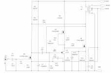
The original circuit is getting retooled so that it can operate off a single HV supply instead of requiring an additional +30 supply. Hopefully it'll be done in time for a trip to BA16.
- Status
- Not open for further replies.
- Home
- Amplifiers
- Pass Labs
- Das ist aber Schade...