Ouch !!!!!80% dissipation
There you have it.
true ... in their case, because they run tubes Class C, meaning basically as switches, meaning dissiption is minimized, big time., but all of the old time HAM operators I know claim cathode current is what kills a tube.
in that case, second killer, current, becomes the most significant.
Sadly it does not apply to Audio amplifiers, where tubes operate as variable resistors instead s switches and also have important idle dissipation.
I got my hifi amp on at least 10 hours a day and takes it's toll on tubes. New tube (NOS) is rated for 1000 hours, the new stuff who knows. NOS tubes last me almost a year, modern ones half that at best.
since the OP seems to have accumulated some statistics on tube failures in his amp, it would be interesting to know, how tubes failed:
filament, arcing, parameter degradation ... ?
do they fail right at power-on from cold, or sometime during the day ?
also, assuming the ouputs fail, and there are 4 of them in the amp, do you say one tube out of 4 fails every half year or does it mean you have to replace a tube every 6 weeks or so on average ?
Last edited:
We already spoke about that. If the tubes only survives 1000h then the amp is broken ( misusing the tubes in some way)since the OP seems to have accumulated some statistics on tube failures in his amp, it would be interesting to know, how tubes failed:
filament, arcing, parameter degradation ... ?
do they fail right at power-on from cold, or sometime during the day ?
also, assuming the ouputs fail, and there are 4 of them in the amp, do you say one tube out of 4 fails every half year or does it mean you have to replace a tube every 6 weeks or so on average ?
Hello,
here is a german book for this: -> https://raumladung.files.wordpress....en_gebrauchsverlaengerung_rundfunkroehren.pdf
It says a lot about making the tube life longer...
here is a german book for this: -> https://raumladung.files.wordpress....en_gebrauchsverlaengerung_rundfunkroehren.pdf
It says a lot about making the tube life longer...
From the "Amplifier HandbooK" 1966, McGraw-Hill, ed. by Richard F. Shea:
"The most significant factor affecting tube life in normal applications is cathode heating power. A normal application is one in which end of life is determined by depletion of the cathode and not by sudden-death causes such as mechanical or severe overload failures."
"Whenever a range of heater or filament voltages is specified, there is a life advantage to be obtained with operation at lower values of voltage, provided the voltage regulation in application is adequate to keep the voltage with the specified range. A general rule of thumb that can be used is that a 5 per cent reduction in heater voltage will increase cathode life 100 percent. This is reasonably accurate with thoriated tungsten tubes but is quite approximate with oxide-coated tubes whose complex chemistry makes accurate predictions difficult." (the cathode must be able to maintain sufficient emission for the application too)
"Thoriated tungsten cathodes (xmit tubes) have very predictable life under controlled conditions of environment. Normal end of life in this cathode occurs when the surface layer of tungsten carbide is depleted. In well-processed tubes operated conservatively, this decarburation rate is determined by the operating temperature of the cathode rather than the cathode emission current used."
"Oxide-type cathode life is affected by innumerable internal and external environmental factors. Life is greatly affected by manufacturing processing, internal tube materials, and tube construction. From the user standpoint, oxide cathode life, unlike that of thoriated tungsten, is detrimentally affected by increased cathode emission current density requirements. No precise relationship exists but the total D-C cathode current in CW operation, or RMS current in pulsed service, provide some relative indication of expected life."
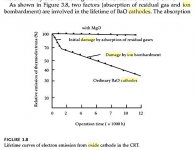
"High plate voltages cause the plate and the tube envelope walls to be bombarded with higher-energy electrons than when lower plate voltages are used. This tends to dislodge absorbed gases, which in turn may "poison" the cathode and reduce its emission capabilities. High positive grid voltages may also cause gas release and, in addition, may cause particles of cathode coating to be torn from a coated cathode by electrostatic attraction, because of the proximity of the grid and cathode."
"Screen current must be carefully controlled as most screens have relatively low dissipation rating, and failure to check screen current in all modes of operation of a circuit may result in excessive screen dissipation and drastically shortened tube life. This is especially true in audio power amplifiers where high input-signal voltages may drive the screen current up to values far in excess of the zero-signal value, and in r-f power amplifiers where removal of the load from the plate circuit of the tube may cause the screen current to soar. " (audio too)
"Grid currents may be classified as "positive" or "negative," with the positive being those which are used to produce negative bias and the negative being those which are detrimental. The negative currents include gas current, grid emission, and leakage current. Gas current flows because positive gas ions are attracted to the negative-bias grid and are neutralized by electrons flowing from the negative pole of the external circuit to the grid. If there is a resistive component in the external grid circuit, a voltage will be developed across it which is of a polarity to cause the grid to be made more positive with respect to the cathode and thus cause a reduction in negative bias. In the worst case the condition will become cumulative; that is, the reduction of bias will cause more current to flow, more heat dissipation, and more evolution of gas, and the tube will "run away" to ultimate destruction. It is for this reason that manufacturers recommend maximum values of grid-circuit resistance. Although it is commonly recognized that vacuum tubes do not have perfect vacuums, it is not generally realized that gas currents in tubes usually result from gas being released by the metal parts or the envelope because of heat or electrolysis. Thus a given tube may show gas current under high dissipations, envelope temperatures, or anode voltages but none at lower temperatures and voltages."
and from Landee/Davis/Albrecht "Electronic Designers' Handbook":
"positive ion bombardment severely damages the emitter surface, and for this reason oxide-coated emitters are only used in tubes having anode voltages less than about 1,000 volts except in special cases."
"The most significant factor affecting tube life in normal applications is cathode heating power. A normal application is one in which end of life is determined by depletion of the cathode and not by sudden-death causes such as mechanical or severe overload failures."
"Whenever a range of heater or filament voltages is specified, there is a life advantage to be obtained with operation at lower values of voltage, provided the voltage regulation in application is adequate to keep the voltage with the specified range. A general rule of thumb that can be used is that a 5 per cent reduction in heater voltage will increase cathode life 100 percent. This is reasonably accurate with thoriated tungsten tubes but is quite approximate with oxide-coated tubes whose complex chemistry makes accurate predictions difficult." (the cathode must be able to maintain sufficient emission for the application too)
"Thoriated tungsten cathodes (xmit tubes) have very predictable life under controlled conditions of environment. Normal end of life in this cathode occurs when the surface layer of tungsten carbide is depleted. In well-processed tubes operated conservatively, this decarburation rate is determined by the operating temperature of the cathode rather than the cathode emission current used."
"Oxide-type cathode life is affected by innumerable internal and external environmental factors. Life is greatly affected by manufacturing processing, internal tube materials, and tube construction. From the user standpoint, oxide cathode life, unlike that of thoriated tungsten, is detrimentally affected by increased cathode emission current density requirements. No precise relationship exists but the total D-C cathode current in CW operation, or RMS current in pulsed service, provide some relative indication of expected life."
"High plate voltages cause the plate and the tube envelope walls to be bombarded with higher-energy electrons than when lower plate voltages are used. This tends to dislodge absorbed gases, which in turn may "poison" the cathode and reduce its emission capabilities. High positive grid voltages may also cause gas release and, in addition, may cause particles of cathode coating to be torn from a coated cathode by electrostatic attraction, because of the proximity of the grid and cathode."
"Screen current must be carefully controlled as most screens have relatively low dissipation rating, and failure to check screen current in all modes of operation of a circuit may result in excessive screen dissipation and drastically shortened tube life. This is especially true in audio power amplifiers where high input-signal voltages may drive the screen current up to values far in excess of the zero-signal value, and in r-f power amplifiers where removal of the load from the plate circuit of the tube may cause the screen current to soar. " (audio too)
"Grid currents may be classified as "positive" or "negative," with the positive being those which are used to produce negative bias and the negative being those which are detrimental. The negative currents include gas current, grid emission, and leakage current. Gas current flows because positive gas ions are attracted to the negative-bias grid and are neutralized by electrons flowing from the negative pole of the external circuit to the grid. If there is a resistive component in the external grid circuit, a voltage will be developed across it which is of a polarity to cause the grid to be made more positive with respect to the cathode and thus cause a reduction in negative bias. In the worst case the condition will become cumulative; that is, the reduction of bias will cause more current to flow, more heat dissipation, and more evolution of gas, and the tube will "run away" to ultimate destruction. It is for this reason that manufacturers recommend maximum values of grid-circuit resistance. Although it is commonly recognized that vacuum tubes do not have perfect vacuums, it is not generally realized that gas currents in tubes usually result from gas being released by the metal parts or the envelope because of heat or electrolysis. Thus a given tube may show gas current under high dissipations, envelope temperatures, or anode voltages but none at lower temperatures and voltages."
and from Landee/Davis/Albrecht "Electronic Designers' Handbook":
"positive ion bombardment severely damages the emitter surface, and for this reason oxide-coated emitters are only used in tubes having anode voltages less than about 1,000 volts except in special cases."
Last edited:
Anatoliy, do you run this open-loop? I use a power differential stage with 6S19P that sounds so good that I had no inclination to even use Plate-Grid feedback; if you don't need high power this is hard to beat and the first set of tubes lasted about 5 years (and they cost peanuts anyway).
Yes, they are quite good to be run open-loop in class A P-P.
So heater power looks to be the 1st most significant life factor for oxide tubes. Just a 5% heater voltage reduction looks quite powerful. (must still meet the emission requirements of the circuit)
For the second significant life factor, the reliability publications just say tube power dissipation. I think that actually jives with the Amplifier Handbook details given above, since released gas quantity would be proportional to heating, and the ionization of the gas proportional to the plate current, and then the ion energy would be proportional to the plate voltage (ie, cathode damage per ion). Net result: damage proportional to tube dissipation.
Probably not a super quantitative relation however, since there may be an ion energy threshold for cathode damage to occur, and high plate current (but low plate voltage) might just hit saturation (ionization) of the available gas. Cooling the glass envelope should help some too.
Last edited:
Don, it depends on tubes. Since I come back to tubes, I don't use "audio" tubes because despite they are cheap in manufacturing they are more expensive than more expensive in manufacturing military tubes. Yes, grids are getting evaporated, cathodes loose emission when poisoned, and so on. Different tubes have different weak points. I had 2 cases when GU-50 tubes restored themselves heating anodes up to orange colour. But I never run them with red control grids.
Here I have some pics from "for authorized personnel only" book regarding 6P15P tube...
...particularly dependence of parameters on a filament voltage.
Here I have some pics from "for authorized personnel only" book regarding 6P15P tube...
...particularly dependence of parameters on a filament voltage.
An externally hosted image should be here but it was not working when we last tested it.
There may be a limit to how low one should lower the heater power (besides meeting emission requirements). One publication mentioned that the space charge around the cathode helps protect against ion bombardment by neutralization. Lowering the heater voltage would reduce that protection. So there is likely some crossover point where cathode poisoning becomes the dominating factor instead.
With lower heater power, beyond that point, being counter-productive.
Idea:
The electrons close to the cathode have low velocities. By putting a modest axial magnetic field along the cathode length (could be permanent magnets), the electrons would spend more time near (circling) the cathode, providing better space charge protection. From previous curve tracer experiments, this makes for a higher Rp and lower gm tube however. Nothing for free!
Last edited:
Re: Anatoly
"Right picture: anode current, transconductance, screen grid current."
Versus heater voltage?
Looks like one would not want to drop below 5 Volts on a 6.3 V heater.
"Right picture: anode current, transconductance, screen grid current."
Versus heater voltage?
Looks like one would not want to drop below 5 Volts on a 6.3 V heater.
Last edited:
Re: Anatoly
"Right picture: anode current, transconductance, screen grid current."
Versus heater voltage?
Looks like one would not want to drop below 5 Volts on a 6.3 V heater.
Yes, it is what I mean. If 6P15P was designed for 6.3V, I want to run them on at least 6V stable, but not below.
So, all being said, do you consider a wise thing to do is to put a bias switch in a PP amp: providing full bias for power tubes (fixed bias, UL) for listening sessions, and say a half of that current for bias when amp is running background music. B+ being the same in both cases. Considering tube life, of course.
And to contribute a bit, here is an interesting article from AE regarding this topic: http://www.tronola.com/Gillespie2544.pdf
Cheers!
Zoran
And to contribute a bit, here is an interesting article from AE regarding this topic: http://www.tronola.com/Gillespie2544.pdf
Cheers!
Zoran
That Gillespie article is certainly spot on for avoiding surge failures. The heater should power up its current gradually to avoid stress. The B+ and screen V to the output stage should then (after full tube warm-up) come up slowly to avoid shock exciting transients. The B+ and screen V should ramp down at power off to avoid transients. Tube heaters should always be fully warmed up when any cathode current could be drawn. Screen and grid stopper resistors needed for stability.
Here is another online article:
Vacuum power tubes, using old valves, and vacuum tube failures
Fully heated cathodes provide space charge protection from positive ions. Another reason to provide heater pre-warm-up.
Looks like heaters could be operated at the minimum heater V on their datasheet (typically 10% under nominal) if it is regulated to avoid going any lower. (trouble starts below 20% reduction apparently)
Lowering the idle current for background listening might help a little, but most of the ion damage is apparently occurring during high power operation (gas desorbed from surfaces). Would certainly help for a class A or near class A biased amp. Maybe the heaters could be dropped to 20% below nominal (regulated) if the idle current is dropped with low signal power.
I'm still trying to find out if there is some threshold plate voltage where positive ion damage to the cathode begins significantly. If that were high enough, one could design for a B+ below that. It's clear that above +1000 V, unacceptable damage occurs for oxide cathodes.
Looks like MgO added to oxide cathodes largely eliminates the ion bombardment issue. I wonder what oxide formulation they use now (and for NOS too).
--
Attachments
Last edited:
Thank you s-a for your answer, this power up/down sequencing seems like a good excuse to use arduino in a tube amp. And yes, I was talking about A class amp, with power tubes biased at max. rated dissipation at idle.
Cheers!
Zoran
Cheers!
Zoran
Last edited:
One approach would be to use bigger Wattage (or more) tubes for output duty than required (with limited/reduced heater power). Then the tubes would not get so smoking hot inside to release gas (to ionize). As long as the gettering still works.
The TV CRT tubes don't get hot, but do suffer from really HV ion damage. They generally used ion traps in the beam structure to deflect the ions too.
It appears the MgO additive has been in oxide cathodes for some time. But power tubes get hot enough to liberate large quantities of gas from surfaces transiently. So the ion bombardment issue is still significant, but not as significant as heater failure or cathode emission failure from vaporized BaO.
If they didn't (or don't now) evacuate ALL the atmospheric Argon (by N2 back-filling before final pump down), that would be an issue with short lifetime in newer tubes. (Argon won't absorb in getters)
--
Last edited:
Looks like MgO added to oxide cathodes largely eliminates the ion bombardment issue. I wonder what oxide formulation they use now (and for NOS too).
I'm gonna guess that formulation would be determined on a type by type basis in the old days. I hope corners aren't being cut today where they weren't back in the day.
This issue is what drove my decision to use 841s in my Unity-Coupled amp. I was simply looking for a linear smaller-power tube that could handle 400V on the plate at idle. It is amazing how few oxide-coated tubes are rated for idle above 300V. My options were pretty much just power tubes and vertical deflection types. I suspect this has to do with cathode formulations. I ended up choosing a thoriated-tungsten DHT, mostly because it performed as well as any of the oxide-coated options and it looked a lot cooler. I found four sets to buy but I will have to figure out another option, probably EL34, when I use them up.
The reason I think that the cathode materials is the main driver for max plate ratings in a lot of tubes is simply comparisons of tubes like 841 (or 801A) with tubes like a 45 (275V max). Essentially the plate, grid, pin spacing in the designs are very similar. I think the driver for the max rating is ion bombardment on the filament surface and the susceptibility to damage.
This is a copy of a post I made on another forum, haven't edited to be more relevant etc.
The way a cathode works is that emission increases exponentially with temperature towards a limit, such that at absolute zero (zero Kelvin), no electrons are emitted; at room temperature, a few escape. At glowing temperatures, there are enough electrons being "boiled off" to make use of. Due to the exponential curve, you gain very little emission by increasing temperature past where it really gets going.
That means you get no performance benefit from running heaters at higher than specified voltage, only lifetime reduction.
I still can't get a sensible consistent answer about running tubes at lower than recommended heater voltages. Many say tube life is reduced, many other say the opposite.
I would suggest that you get longer life, lower transconductance and perveance (that is lower current capacity). Many highend HiFi Preamps run heaters at lower than recommended voltage. This means that the tubes do not meet full spec when new but maintain that "not quite new spec" way longer than the expected lifetime when operated at full heater voltage
Broskie had a few things to say about heater voltage here:
The Tube CAD Journal, Heater Concerns
If you keep clicking "NEXT" to the 10th page there is a graph of tube transconductance vs lifetime at 5.04V, 6.30V and 7.56V heater supply.
Direct Link The Tube CAD Journal: Voltage regulators for the 2A3
The 6.3 and 7.56 volt curves show the transconductance falling off by 25% fairy quickly over the first 1000 hrs of operation with the 7.56 curve falling off at a higher rate after that. The 5.04 volt curve starts at that 25% low point and basically stays at that point way out to over 5000 hours. Passed the 1000 hour point the 7.56V and 6.3V curves have actually fallen below the 5V curve.
The old tube guys recommended changing a tube when transconductance dropped below 70% of new value but that was because circuits were designed to operate with tubes down to 70% of nominal value - so 70% of new transconductance was considerd to be the end of life point.
If you design the circuits to work with a lower transconductance to start with then it seems you can get VERY extended tube life by running at lower voltage.
Some guys say that you get reduced tube life at low heater voltage and talk about things like cathode poisoning. I think this just applies to big transmitter tubes but possibly to audio output tubes too.
I would therefore not hesitate to run preamp tubes at lower voltage but would perhaps try to keep output tubes near nominal voltage.
Cheers,
Ian
No. An exponential curve means that you get huge increases in emission as you raise the temperature. What you forgot to mention is that almost all electrons very quickly drop back to the cathode; during the brief time between emission and reabsorption they form a space cloud. The bigger the space cloud the quicker they go back to the cathode. Hence the pool of available electrons does not grow so much, but this is not due to emission slowing but returning speeding up.gingertube said:Due to the exponential curve, you gain very little emission by increasing temperature past where it really gets going.
A small drop in heater voltage can increase life (and perhaps reduce noise), provided that a good space charge is still maintained. This means not too much cathode current. Further reduction in heating can reduce life as the space charge gets too weak - this will also start raising shot noise as space charge smoothing will no longer work.I still can't get a sensible consistent answer about running tubes at lower than recommended heater voltages. Many say tube life is reduced, many other say the opposite.
A typical small signal valve has 2-4W of heating and runs 1-10mA of anode current. A typical mid-level output valve has 3-6w of heating and runs 20-50mA of anode current. Hence there is scope for underunning heaters for small valves but not output valves.
- Status
- Not open for further replies.
- Home
- Amplifiers
- Tubes / Valves
- Making tubes last longer by lowering Voltage?