What is the projected dissipation per channel?
Modushop has the new minidissipante cases 120mm height and 300mm deep which have 0.4 W/C dissipation apparently so if they are enough it would be a nice small form factor case for this project!
I was looking at this chassis too, especially since I will be using an external power supply and do not need much extra space. Assuming 1A idle current and 2 x 30 V supply it would be 60 Watts, that gives you 24° above ambient. The 0.4 W/C are probably at a higher temparature gradient though and 'might' be a bit optimistic, but that should still be well within limits. Off course there is only one way to find out ;-)
What is the projected dissipation per channel?
Modushop has the new minidissipante cases 120mm height and 300mm deep which have 0.4 W/C dissipation apparently so if they are enough it would be a nice small form factor case for this project!
Standard bias is about 1 amp with 28V rails = about 60 watts.
.4W/C per channel = 24 deg C above ambient, a standard value.
😎
What is the projected dissipation per channel?
Modushop has the new minidissipante cases 120mm height and 300mm deep which have 0.4 W/C dissipation apparently so if they are enough it would be a nice small form factor case for this project!
Yeah, I was thinking about that cases also... because for 60 Watt dissipation /side those sink will do here in the Netherlands. I have my standard F5 also in a dissipante 3U. ( same heatsinks)
But I don't think you get your transformer in the space left between the brackets and PCBs.

I now have my kit in hand just delivered by Fedex. I am going to wait for Jim "6L6" to finish his build guide and promised video before proceeding with the build. The brackets are a perfect fit for some heatsinks I bought for this project last year from HeatsinkUSA.
How about a some news on how the build guide is coming along Jim?
How about a some news on how the build guide is coming along Jim?
Yeah, I was thinking about that cases also... because for 60 Watt dissipation /side those sink will do here in the Netherlands. I have my standard F5 also in a dissipante 3U. ( same heatsinks)
But I don't think you get your transformer in the space left between the brackets and PCBs.
The internal area is 250mm X 300mm. Enough for a 400VA toroidal (140mm diameter) and the diyaudio PSU PCB (with diode board removed.)
60W should be quite manageable by this heatsink! Nice!!
Now we need to get hifi2000 to make a nice price on drilling the heatsinks for the UMS pattern. Groups buy anyone??
Can we see a picture? 😀
/U.
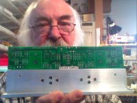
Sorry no working camera. I have not even held one in years. It looks very good though. Heatsink brackets are from the diyaudio supplier HiFi2000. The boards appear to be black or dark blue. Screws and insulators are also included. No instructions so we will have to wait on Jim or wing it ourselves for the brave. I am leaning now to build monos or at least buy 2 200VA transformers and build 2 separate PS in one case. Already having heatsinks I can make the case as big as I want. I have one diyaudio store case for the F6 and another FW M2 in a case I built so it is not a big deal building a custom case. This amplifier deserves to have dual transformers and PS.
I measured and graded the parts by Vgs primarily so that people will be able
to set a bias point before installing VFETs, for obvious reasons.
The VFETs were then sorted in order, and the packers have instructions to
go through them in sequence, so that when you get 2 pair you will find a
close match between the two N's and separately the 2 P's.
I did this so that:
a) audiophile mania for symmetry is satisfied.
b) you could get matched pairs if you buy two sets so as to make the
version with dual pairs of VFETs.
...
😎
just for my understanding of the above mentioned point "b)" and please forgive my ignorance; i am going to build the original dual pair VFET version and have ordered 2x kits as proposed above. my understanding is that i need 4x matched pairs of the VFETs ( 2x the parallel VFETs and 2x for upper and lower VFETs) in order to make sure that the right and left channels are almost exactly the same.
is that correct? do I need and will receive quad machtched pairs?
best regards
I'm just wondering what I can do.
For me, duty costs about ten percent, it is acceptable.
But I must have to pay VAT also, which is a horrible 27%, on the total costs, including duty and shipping costs.
Maybe it is better, if I spend my money on beer. 🙁
For me, duty costs about ten percent, it is acceptable.
But I must have to pay VAT also, which is a horrible 27%, on the total costs, including duty and shipping costs.
Maybe it is better, if I spend my money on beer. 🙁
You can buy beer now and over 10 years you still can buy beer.... but this is one time only, designed by Nelson Pass... need I say more😀🙂
Yes, of course I know. ;-)
But then how will I be able to catch up with Chögyam Trungpa?
This or that.
But then how will I be able to catch up with Chögyam Trungpa?
This or that.
Walter,
I second dady's request as to where to buy the heatsinks that you've provided an attachment picture for on Post #1490. Are they still available, and would you provide the link for us please?
Thank you.
All the Best
Msr. Mojo
I second dady's request as to where to buy the heatsinks that you've provided an attachment picture for on Post #1490. Are they still available, and would you provide the link for us please?
Thank you.
All the Best
Msr. Mojo
The internal area is 250mm X 300mm. Enough for a 400VA toroidal (140mm diameter) and the diyaudio PSU PCB (with diode board removed.)
60W should be quite manageable by this heatsink! Nice!!
Now we need to get hifi2000 to make a nice price on drilling the heatsinks for the UMS pattern. Groups buy anyone??
How high is the toroidal you mentioned?
Because it will be partly under the PCB boards.
Bracket is about 5 cm, PCB also, if I look at this ever funny picture.
Attachments
I want to build two of this amp's for my two boys as a gift from their father. So when I'm around no more they have something beautiful to listen and look at.
( Never to sell by them!!! 🙂 )
But is there an easy implementation for a, say 5 ampere current limiter, so when they short outputs for a small time, the VFETs are not immediately fried ?
I think this must be possible with already a regulated supply onboard?
Thanks,Walter
( Never to sell by them!!! 🙂 )
But is there an easy implementation for a, say 5 ampere current limiter, so when they short outputs for a small time, the VFETs are not immediately fried ?
I think this must be possible with already a regulated supply onboard?
Thanks,Walter
- Home
- Amplifiers
- Pass Labs
- Sony vFET Amplifier Part 2