Hi,
I'm having a problem with LTSpice that seems to be some software problem.
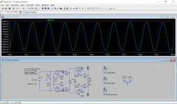
Look at the Diagram below and its responses.

and here is the LTSpice file
View attachment LT_Spice_Problem.asc
When offering a signal to the input, up to the output of the second set of OPA's, the signal is perfectly symmetrical around zero, see V(U3)=V(U2)-V(U1).
But after being processed by the filter with the 2 time constants (R4-R5-R20-C6), the signal starts heavily shifted shifted upwards,
and it takes at least 20msec before it has reached its stable symmetrical position around zero, see V(Out)*10
No matter what I try, this effect remains and it seems having to do with the dual time constants,
because the filter before this one with only one time constant (R2-R3-C5) responds free of any such problem.
Hans
I'm having a problem with LTSpice that seems to be some software problem.
Look at the Diagram below and its responses.
and here is the LTSpice file
View attachment LT_Spice_Problem.asc
When offering a signal to the input, up to the output of the second set of OPA's, the signal is perfectly symmetrical around zero, see V(U3)=V(U2)-V(U1).
But after being processed by the filter with the 2 time constants (R4-R5-R20-C6), the signal starts heavily shifted shifted upwards,
and it takes at least 20msec before it has reached its stable symmetrical position around zero, see V(Out)*10
No matter what I try, this effect remains and it seems having to do with the dual time constants,
because the filter before this one with only one time constant (R2-R3-C5) responds free of any such problem.
Hans
Last edited by a moderator:
May I add to the discussion that the solution offered is an obvious workaround, but I was in fact asking for a possible reason why LTSpice is responding this way.
In the shown diagram, because of the balanced nature, there is no way to explain how a single capacitor could shift the signal upwards,
so it seems to having to do with the simulation software itself.
Is there any possibility to communicate with the development team?
Hans
In the shown diagram, because of the balanced nature, there is no way to explain how a single capacitor could shift the signal upwards,
so it seems to having to do with the simulation software itself.
Is there any possibility to communicate with the development team?
Hans
In the time domain, use simple differential probing (click on one node and drag cursor to other node, then release) rather than behavioral sources to plot difference voltages, those can be compromised in the time domain analysis :
http://ltwiki.org/?title=B_sources_(complete_reference)
EDIT: This is not your problem, I ran the sim. The problem IS the time constant (around C6) itself and its settling time. Clearly not a bug.
http://ltwiki.org/?title=B_sources_(complete_reference)
EDIT: This is not your problem, I ran the sim. The problem IS the time constant (around C6) itself and its settling time. Clearly not a bug.
Last edited:
Thanks for your reply.In the time domain, use simple differential probing (click on one node and drag cursor to other node, then release) rather than behavioral sources to plot difference voltages, those can be compromised in the time domain analysis :
B sources (complete reference) - LTwiki-Wiki for LTspice
Wiki responds with this message: There is currently no text in this page. You can search for this page title in other pages, or search the related logs, but you do not have permission to create this page.
I can only repeat that I see no way how in a balanced circuit, no matter what C6 is doing by having a charge or not, can result in the upward shifting of the balanced signal at the output.This is not your problem, I ran the sim. The problem IS the time constant (around C6) itself and its settling time. Clearly not a bug.
Both V(Out+) and V(Out-) could be shifted in opposite directions, but V(Out)=V(Out+)-V(Out-) cannot be shifted in any way by C6.
So a bug after all?
Hans
P.S.1 Dragging and clicking as you suggested gives exactly the same result as the behavioral source
P.S.2 Placing a 5 Volt voltage source in series withC6, does not alter the behaviour in any way, although C6 has now to be charged to 5 Volt!
Last edited:
There seems to be an issue with the model for the LT6203. If you do a .op simulation using the LT6203, there are some unexpected DC offsets around the circuit (e.g. +6.7mV at both outputs and +1.38mV at both inputs). Replacing the LT6203 with (almost at random) the LT1001, the offsets disappear and the circuit behaves as expected.
I've no idea whether the model is the issue or whether the LT6203 itself is the issue. Personally I rather suspect the accuracy of the model.
If you wish to pursue this further, I suggest you pop over to the Yahoo LTspice forum to ask them about the model. You will need to join first if you are not already a member. They are a very knowledgeable lot over there, and if there is a bug in the LT6203 model, they will pass it on to Mike Engelhardt, the LTspice developer.
There is an email address for bug reports in the Help...About menu, but I think it is much better to go via the LTspice forum, especially as I think this is not a bug within LTspice, but rather a bug within the LT6203 model.
Hope this helps.
Stephen
Hi Stephen,
Thanks for your constructive contribution regarding the LT6202.
I have also tried a dozen different OPA's, like the LT1395, LT1807, LT1028 etc.but they all behave the same.
I will follow your advise and join the Yahoo LTSpice forum.
Hans
Thanks for your constructive contribution regarding the LT6202.
I have also tried a dozen different OPA's, like the LT1395, LT1807, LT1028 etc.but they all behave the same.
I will follow your advise and join the Yahoo LTSpice forum.
Hans
KSTR, you are right, this is exactly as weird and not conforming to a real world situation.
So the simulation is making up something that should not be there.
Hans
So the simulation is making up something that should not be there.
Hans
Hans
You are right in so far as this behaviour is shown with other opamps too.
However, I've had another look at this and have come to the conclusion that there is nothing wrong with LTspice, and that Mooly is perfectly correct in suggesting that you start plotting after a few cycles have taken place.
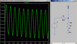
Take the circuit of the output as shown by KSTR. The DC voltages at t=0 (all zero) are not the same as the instantaneous voltages at t_n=n(1/f), where n is an integer.
Taking as an example the voltage v at the junction of the capacitor and the 677R resistor (in KSTR's circuit):
at t=0, v=0
at n=10, t=10mS, v=-526uV
In other words, after the circuit has reached a steady state, the instantaneous voltages at t_n are not the same as at t=0.
The same applies to the output circuit in your original circuit. All this, of course, is the result of the phase difference between AC voltages and currents in a capacitor.
Note that there is another complication in the input circuit due to the capacitances at the inputs of the opamp. The zero volt crossover points of the differential input voltage are not at exactly t_n. Removing R13 and R14 in your circuit "corrects" this for the purpose of understanding the circuit.
I hope this all makes sense! Incidentally, I still find the initial DC conditions with the LT6203 rather strange.
Stephen
You are right in so far as this behaviour is shown with other opamps too.
However, I've had another look at this and have come to the conclusion that there is nothing wrong with LTspice, and that Mooly is perfectly correct in suggesting that you start plotting after a few cycles have taken place.
Take the circuit of the output as shown by KSTR. The DC voltages at t=0 (all zero) are not the same as the instantaneous voltages at t_n=n(1/f), where n is an integer.
Taking as an example the voltage v at the junction of the capacitor and the 677R resistor (in KSTR's circuit):
at t=0, v=0
at n=10, t=10mS, v=-526uV
In other words, after the circuit has reached a steady state, the instantaneous voltages at t_n are not the same as at t=0.
The same applies to the output circuit in your original circuit. All this, of course, is the result of the phase difference between AC voltages and currents in a capacitor.
Note that there is another complication in the input circuit due to the capacitances at the inputs of the opamp. The zero volt crossover points of the differential input voltage are not at exactly t_n. Removing R13 and R14 in your circuit "corrects" this for the purpose of understanding the circuit.
I hope this all makes sense! Incidentally, I still find the initial DC conditions with the LT6203 rather strange.
Stephen
Last edited:
Sorry, but that isn't true. LTspice is not making up things. Build the RC circuit, feed it with a 1kHz sine wave starting at zero and look at the waveform (capture it with a sound card or a DSO). You'll see the exact same thing.KSTR, you are right, this is exactly as weird and not conforming to a real world situation.
So the simulation is making up something that should not be there.
Exactly!All this, of course, is the result of the phase difference between AC voltages and currents in a capacitor.
Sorry, but that isn't true. LTspice is not making up things. Build the RC circuit, feed it with a 1kHz sine wave starting at zero and look at the waveform (capture it with a sound card or a DSO). You'll see the exact same thing.
Exactly.
The time constant of this RC is ~3ms, and after about 5x the time constant (15ms) steady state conditions are reached with little error. Matches perfectly.
Since it was almost a flick of a switch, I could not resist to do the test in real life.
This is the result, blue is input, red is output.

I also made an overlay of the simulation that KSTR did on my results, and as you can see, green and red are exactly on top of each other.

So KSTR, Stephen and LTspice are all telling the truth, and I'm fully convinced by now.
Thanks for all your contributions.
Hans
This is the result, blue is input, red is output.
I also made an overlay of the simulation that KSTR did on my results, and as you can see, green and red are exactly on top of each other.
So KSTR, Stephen and LTspice are all telling the truth, and I'm fully convinced by now.
Thanks for all your contributions.
Hans
My eyes fill with tears, IRL and simulation match over 🙂
If such a basic thing already fills your eyes with tears, you must be weeping quite a lot 😀
My memory is that it was Chuchundra the musk-rat who cried a lot, not Rikki Tikki Tavi the heroic mongoose. 🙂My eyes fill with tears, IRL and simulation match over 🙂
I have had a few surprises with LTSpice too, among them, finding out that some sine wave oscillator circuits will not self-start unless I manually reduce the minimum time step before running the simulation.
-Gnobuddy
- Status
- Not open for further replies.
- Home
- Design & Build
- Software Tools
- LTSpice Error?