Resolution is not so very great with a system like this. Analog catches subtleties that FLAC won't.
Care to explain that?
Iv'e heard great digital. When the JBL M2 was just lanched Charles Sprinkle sat me down in one of the JBL listening rooms and played his FLAC files. It was good. It imaged like crazy. Still Plastic sounding though. There have been other times. Kevin Gray has great digital playback too.Care to explain that?
But I have heard all analog that beats the pants off of ANY digital system.
TechDAS TT feeding a Constellation (another JC masterpiece 🙂 ) Audio system. It's the cost of a house but Wow! Wow! Wow!.
Kevin Gray's mastering room. When he brings out a test cut disk and pops it on his lathe the resolution is not sublte. And if that lathe plays a digitally sourced vinyl cut the soundstage collapses dramatically. I've been in KG's mastering room 3 times for a few hours 2 of those times and one time for 6 hours.
I could go on but I have orders to fill.
BTW 20 years ago I would have told you that digital is the best and SACD will solve all of our audio problems. It just hasn't worked out that way. 😱
Care to explain that?
He prefers a different medium for whatever reason, which is stated as absolute truth. Bit perfection is just magical thinking. 😀
We really can't talk, our references are too far apart. A nanovoltmeter is a bit different than an FFT analyzer. If you played a bit with the gear you would get an understanding of what it can and cannot do. But don't worry other folks will probably try the tests then we can compare results.
Having a device which has a readout with 9 digits to the right of the decimal point is not the same as performing accurate measurements 9 digits to the right.
It is very easy to achieve stable repeatable results using setups like that. Unfortunately,a stable readout is not the same as having an accurate reading.
John
Repetitive, long term experience. Same results every time.He prefers a different medium for whatever reason, which is stated as absolute truth. Bit perfection is just magical thinking. 😀
Last edited:
You do realize that gives you a lot of time to convince yourself of something? Or that you have a preference? That's fine. But to say one is "better" is, well, tiring. Especially when you make generalizations.
Richard - there's a Hong Kong retailer selling the full range of Miulticaps on Ebay.
prices look like US retail, do you think their real?
They might be real.... you can ask mfr (REL CAP in California) if they are a distributor or if they sold to them. Or you can send me one and I can destructively examine it.
-RNM
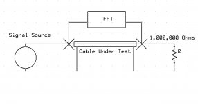
did we ever get a sketch of the test setup. I have enough hardware in my warehouse to test it if I knew better the way to test it. A picture is worth a thousand words.
I have a Kiethley 823 nanovolt amplifier/meter (high Z IP), HP 4328A milliOhm meter (1 millOhm fs), TEK differential comparitor and diff amps, Network analyzers from Dc to 6GHz, all kinds of FFT etal...... ETC What are we measuring.... show me a test setup sketch.
THx-RNMarsh
I have a Kiethley 823 nanovolt amplifier/meter (high Z IP), HP 4328A milliOhm meter (1 millOhm fs), TEK differential comparitor and diff amps, Network analyzers from Dc to 6GHz, all kinds of FFT etal...... ETC What are we measuring.... show me a test setup sketch.
THx-RNMarsh
did we ever get a sketch of the test setup. I have enough hardware in my warehouse to test it if I knew better the way to test it. A picture is worth a thousand words.
I have a Kiethley 823 nanovolt amplifier/meter (high Z IP), HP 4328A milliOhm meter (1 millOhm fs), TEK differential comparitor and diff amps, Network analyzers from Dc to 6GHz, all kinds of FFT etal...... ETC What are we measuring.... show me a test setup sketch.
THx-RNMarsh
One test source can be a sine wave of 10 millivolts or less. The other test is best done with a noise source filtered to about 1/3 octave ISO filter curve.
Attachments
Be tired then. I cut my multi-track recording in 1980. I've been on a continuous audio path since.You do realize that gives you a lot of time to convince yourself of something? Or that you have a preference? That's fine. But to say one is "better" is, well, tiring. Especially when you make generalizations.
I worked at Alesis all through to 90's. Saw the birth of affordable multitrack digital recording. It was digital heaven there. I drank the digital Kool-aid. I un-drank it in the late 00's
Last edited:
One test source can be a sine wave of 10 millivolts or less. The other test is best done with a noise source filtered to about 1/3 octave ISO filter curve.
What is the impedance of the fft box?
What is the impedance of the fft box?
I can use one of mine and select 100K input Z. Can add input atten for higher Z if I have to.
THx-RNMarsh
Sorry, that was the theorist in me talking. When I say "nanovoltmeter" I mean any instrument which claims to be able to give a numerical indication (including from a graph) of very small signal voltages. FFTs have artifacts, so you can't simply assume that what you read from the graph is a measurement; it is actually merely raw data which has to be analysed. For example, FFTs can sometimes be fooled by harmonics or sub-harmonics due to their finite windowing time. Careful choice of windowing function can help. I'm sure the expert experimenters on here know far more than I do about FFT peculiarities.simon7000 said:A nanovoltmeter is a bit different than an FFT analyzer.
Yes.jneutron said:Having a device which has a readout with 9 digits to the right of the decimal point is not the same as performing accurate measurements 9 digits to the right.
It is very easy to achieve stable repeatable results using setups like that. Unfortunately,a stable readout is not the same as having an accurate reading.
What is the impedance of the fft box?
More importantly the exact locations of all junctions, and nV with 1M/10M scope probes?
This reminds me of the guy who said there was no point to building certain electronics now, as one could simply use an ADC with 35 bit resolution.More importantly the exact locations of all junctions, and nV with 1M/10M scope probes?
More importantly the exact locations of all junctions, and nV with 1M/10M scope probes?
Yah, when you look at the full manual writeup for HP equipment, how they control the junctions and loops is totally awesome and well beyond simply connecting the clip leads.
John
More importantly the exact locations of all junctions, and nV with 1M/10M scope probes?
A 1M scope probe is a piece of wire. The scope's input impedance is 1M. When you use a probe with a 9M resistor at the tip with a compensating capacitor you get 10M and a 10/1 Divider. you cam also adjust the trimmer for good square wave response to compensate for the cable and input capacitance.
The measurement may be taken right at the test jacks terminal. You are looking at around .1 ohms. You can even use an isolation transformer at the test points.
The open issue is what happens when you reverse the cable under test. It really is a simple experiment. If you are careful to dress the cable under test the same way each direction you are certainly reducing the variables. Multiple runs at different times might show outside influences. But it would take less time to run the experiment than.....
Last edited:
I can use one of mine and select 100K input Z. Can add input atten for higher Z if I have to.
THx-RNMarsh
An input attenuator when looking at 1 nanovolt levels?
Ed, you'd be better off putting the fft box directly across the connectors to look at contact non linearities. No loop, no capacitance to ground to worry about. That way, you could look at attovolts..
John
- Status
- Not open for further replies.
- Home
- Member Areas
- The Lounge
- John Curl's Blowtorch preamplifier part II