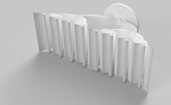
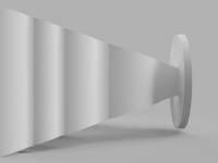
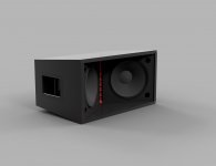
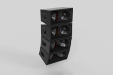
Hi guys, awhile ago I designed a waveguide for a line array speaker just for fun. Now I'm revisiting the design to finally use it. The waveguide is intended to be used with a JBL (Selenium) D220Ti compression driver. The crossover frequency should be around 2-2.5kHz. This driver would be paired up with two Kappa-Pro-10As.
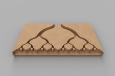
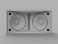
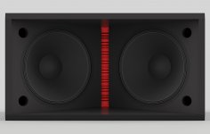
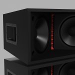
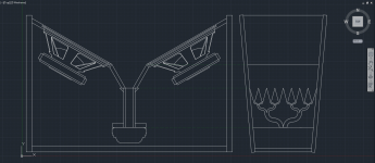
The goal of this waveguide is to get the 1" exit of the compression driver spread to the entire height of the horn, which is the inside height of the enclosure, while maintaining a very shallow depth.
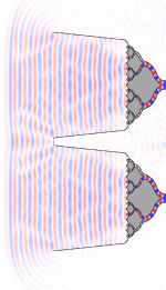
Every time the path for the compression driver splits the area of each path is halved. After leaving the waveguide, the horn has a 120 degree coverage angle for the horizontal axis and 10 degrees for the vertical axis.
Some questions I have:
Does halving the area of the path each time the amount of paths double affect how the waveguide to horn transition preform? Since the wave is only given a total of ~1in² then within a half inch expands at a 120 degree angle. Perhaps making the waveguide expand each time the paths double? In other words, the waveguide starts with one path of ~1in², but instead of ending with 8 paths of ~.125in², it ends with 8 paths of ~1in².
For either of the previous described waveguides, would it be notably beneficial to add a middle segment to the horn with a 60 degree horizontal expansion?
Lastly, are there any other freeware applications worth while to use to simulate the acoustics of a waveguide? I'm currently using Wavefront Simulator, which does what I need, but there are a couple glitches that make importing the file a bit cumbersome. Also the software is a bit old and is only written for single cpu core usage.
Any feedback is appreciated!
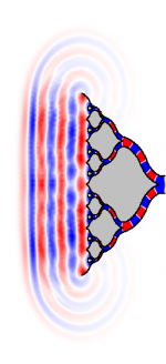
(note: The first simulation is done at ~13.5kHz. The second simulation is done at ~19.5kHz


Last edited:
I would keep the "halving area of each path at the split" concept. However, make the area continuously increase along the whole path. What you have now is equivalent to a tube in terms of expansion rate (i.e. it doesn't expand). Then again maybe that's what you want, it would be worth modeling across many frequencies to see what happens to frequency response (if your software will output magnitude given a constant input level).
Last edited:
Bounce
Here are some initial thoughts on your design:
1) It is an Acoustic Lens, only at the exit is there presently an expansion.
2) You might want to consider a quad division at the throat entry and there after to get bifurcation in two dimensions instead of just one at each node.
3) Before the second node, implement a transition to rectangular passageway cross-sections.
4) You can produce this structure as well as the 2-way structure on a 3D printer.
5) With expansion, ever time cross-section area doubles (or quadruples), implement bifurcation node again either 2-way or 4-way.
6) Note that air flow resistance increases as passage number increases and/or passage cross-section decreases. When this occurs, air viscosity and elastic non-linearity become an issue.
This way you get a passage tree in three dimension.
If you are a student you may be able to get access to this:
https://www.comsol.com/acoustics-module
Regards,
WHG
Would expanding the area by increasing the width of the waveguide achieve that too? The render below has a 30 degree expansion horizontally but still 0 degree vertical. I left some parts out for the render to see the inside easier. It would be quite difficult to cut that out though.
View attachment 559370View attachment 559371
Here are some initial thoughts on your design:
1) It is an Acoustic Lens, only at the exit is there presently an expansion.
2) You might want to consider a quad division at the throat entry and there after to get bifurcation in two dimensions instead of just one at each node.
3) Before the second node, implement a transition to rectangular passageway cross-sections.
4) You can produce this structure as well as the 2-way structure on a 3D printer.
5) With expansion, ever time cross-section area doubles (or quadruples), implement bifurcation node again either 2-way or 4-way.
6) Note that air flow resistance increases as passage number increases and/or passage cross-section decreases. When this occurs, air viscosity and elastic non-linearity become an issue.
This way you get a passage tree in three dimension.
If you are a student you may be able to get access to this:
https://www.comsol.com/acoustics-module
Regards,
WHG
Last edited:
Here are some initial thoughts on your design:
1) It is an Acoustic Lens, only at the exit is there presently an expansion.
2) You might want to consider a quad division at the throat entry and there after to get bifurcation in two dimensions instead of just one at each node.
3) Before the second node, implement a transition to rectangular passageway cross-sections.
4) You can produce this structure as well as the 2-way structure on a 3D printer.
5) With expansion, ever time cross-section area doubles (or quadruples), implement bifurcation node again either 2-way or 4-way.
6) Note that air flow resistance increases as passage number increases and/or passage cross-section decreases. When this occurs, air viscosity and elastic non-linearity become an issue.
This way you get a passage tree in three dimension.
If you are a student you may be able to get access to this:
https://www.comsol.com/acoustics-module
Regards,
WHG
I like the idea of a quad division. The issue with my previous posted 'expanding design' and the 'quad division design' is that, like you said, are possible with a 3D printer. I don't readily have access to a 3D printer, but I do own a CNC machine. I think I need to stick with the basics and make the design 2D.
I took a look at comsol and it does exactly what I'd want but I can't seem to find the student version. I wish Simulation CFD (from Autodesk) did acoustics, it only does puffs of air.
I wanted to see how making the wave take two 90 degree turns around a radius would affect the flow. since theoretically the 2nd turn would undo the skew from the first turn. The simulation shows that is the case. Unfortunately the software I'm using doesn't give an output of how the lens performs. (At least from what I've found) The transition between the lens and the horn has an expansion of 30 degrees for about 1.8". I made size of the box slightly bigger and added a section with an expansion of 60 degrees before the part that expands at 120 degrees.
Starting at 15kHz there started to be a breakup. I was surprised that its fixed itself by the next section.
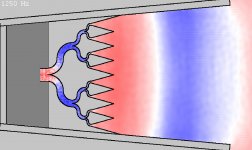
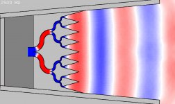
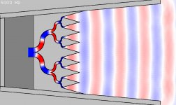
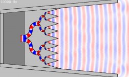
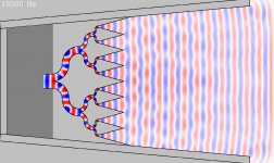
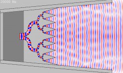

Starting at 15kHz there started to be a breakup. I was surprised that its fixed itself by the next section.


Last edited:
Acoustic Lens Potpourri
1) Recommend hyperbolic cylinder segment [1] for vertical boundaries.
2) When passage transverse dimensions become comparable to wavelength, standing waves will be formed across them and be observed as irregularities in frequency response.
3) I have attached some articles [2]-[6 ] that may be helpful.
4) It is only the COMSOL license that is different.
https://www.comsol.com/products/licensing
Contact them they may provide additional help.
https://www.comsol.com/contact?gclid=CLGnoqS_8s0CFQctaQodUxwNAQ
Also check with the physics department/college to see if you can get access to it as part of your dissertation effort.
Regards,
WHG
I like the idea of a quad division. The issue with my previous posted 'expanding design' and the 'quad division design' is that, like you said, are possible with a 3D printer. I don't readily have access to a 3D printer, but I do own a CNC machine. I think I need to stick with the basics and make the design 2D.
I took a look at comsol and it does exactly what I'd want but I can't seem to find the student version. I wish Simulation CFD (from Autodesk) did acoustics, it only does puffs of air.
1) Recommend hyperbolic cylinder segment [1] for vertical boundaries.
2) When passage transverse dimensions become comparable to wavelength, standing waves will be formed across them and be observed as irregularities in frequency response.
3) I have attached some articles [2]-[6 ] that may be helpful.
4) It is only the COMSOL license that is different.
https://www.comsol.com/products/licensing
Contact them they may provide additional help.
https://www.comsol.com/contact?gclid=CLGnoqS_8s0CFQctaQodUxwNAQ
Also check with the physics department/college to see if you can get access to it as part of your dissertation effort.
Regards,
WHG
Attachments
Acoustic Lens Adendum
5) Does your CNC machine have a Z-Axis?
6) The herringbone pattern occurring a high frequencies can be mitigated through passage expansion over the entire passage length, with passages terminated by apertures dispersed over an arc normal to horn boundries.
Regards,
WHG
5) Does your CNC machine have a Z-Axis?
6) The herringbone pattern occurring a high frequencies can be mitigated through passage expansion over the entire passage length, with passages terminated by apertures dispersed over an arc normal to horn boundries.
Regards,
WHG
- Status
- Not open for further replies.
- Home
- Loudspeakers
- Multi-Way
- Line Array Waveguide Design
