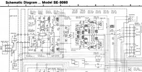
This is an old power amp from about 1978, the chassis is very well built.
I wonder if is any way to improve it?
Using the input switch coupled as DC is the easiest way to improve the sound.
Make sure the 0.68 ohm emitter resistors are good. The main electrolytics may
well need replacement.
Last edited:
Thank, but Is was thinking of the amps topology.
Yes, but you should get it working like new first, to see whether it actually needs any improvement.
If you re-cap, wich you definitly should do, you could change the power supply capacitors for ones with a bigger capacity (and voltage rating, if it fits) and upgrade the bridge rectifier for a more sturdy one (25A or more, 600V or more).
You could change R103 for 15K to lower the gain and get closer to a DC-balanced input pair, giving you less DC offset at the outputs and more adjustability at the volume knob.
Personally, I'd upgrade C1 for a (M)KP type (metallized) foil type capacitor (if it isn't already and you changed R103). Anything above 4µF should make it inaudible while still blocking DC.
If there are carbon composition resistors in the amp, I'd at least check their value, if not change them for metal films, just to be shure.
You could also add a NP0/styroflex/foil-cap at the input after the input capacitor, parallel to R103, with around 33-100pF to attenuate ultrasonic frequencies more (than C223 already does).
But that's just my (unqualified) 2 cents...😉
These go back further then that. I used to repair them in 1974 when I was a service tech at Panasonic in the Chicago Burbs. I suspect 1973 at least.
Mark
Mark
Mark, I don't know for sure, may be it happened earlier in the USA. I come across the Technics flat or brown series when I was living in Sweden in the late seventies.
I bought all the components ,including this power amp after I moved to Canada , used in the eighties. The manual print code is 7708-3. 300 and the Hi Fi Engine put it 1977 - 1981. Technics SE-9060 - Manual - Stereo/Mono Power Amplifier - HiFi Engine
Thanks, Miklos
I bought all the components ,including this power amp after I moved to Canada , used in the eighties. The manual print code is 7708-3. 300 and the Hi Fi Engine put it 1977 - 1981. Technics SE-9060 - Manual - Stereo/Mono Power Amplifier - HiFi Engine
Thanks, Miklos
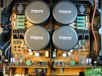
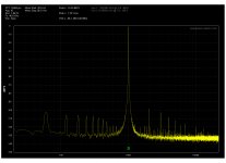
Thanks, 1210. The Amp is a dual mono one, with special low profile electrolytes only 52mm tall. Would be difficult to find. The 60Hz now siting around -100dB at 1kHz 3V in to 8 Ohms. The bridge is fairly big with heatsinks. I'm using the amp DC coupled. It looks like that the resistors in the amp section are the metal film type. I tough R103 would only change the input impedance. I was thinking more like changing the transistors in the output stage for newer type ones and eventually playing with the feedback, but I'm not an EE and that's why I asked for help.
Attachments
I wouldn't mess with the negative feedback side, as there's a DC-offset-correction built-in.
Adjusting R103/104 from 390K to 15K alone should give you a lower noise floor as you can run higher signal-levels for the same gain.
If I understand correctly, R103/104 should match R241/242 for a more balanced input differential pair signal, as this allows the dual-j-Fets µPA63H used in the amp (T101/102) to "correct errors via negative feedback" better. One gets positive phase signal (input) and the other compares that with the negative phase output to cancel any errors that the amp might have produced while amplifying. To do this better, it's usually recommended to match these as closely as possible - but since you have (I hope factory matched) dual-transistors in one package, there shouldn't be much left for you to improve.
Yes, this also "messes" with the input impendance, but anything above 2K should be fine for every source I know, so you'd be fine on that front. Beeing able to "crank the volume knob up further" for the same amplification also means the signal has to travel though less pot-resistance in series to the signal. As you might imagine potentiometers are not "the best" resistors - 40 year old ones don't get better with time, either...depending on your application, you could jumper those, always running maximum volume on the amplifier.
But this depends on you having some volume knob-headroom to start with. Otherwise, the amp, cranked to max-volume, can not amplify your source signal enough for those times you actually want (near) full power. The specs call for 1V of source signal/input sensitivity, so lowering R103/104 (especially as much as I suggested) might do this...
Switching R101/102 from carbon to metal-film might also help with a lower noise floor as well as allow for a better match between channels (service manual only specifies 5%, you could use 1% or better and hand-matching).
If you want to lower distortion, I'd rather get working on the input (and power supply) than the output. The output/current amplification adds very little to the sound compared to the input/voltage amplification, given enough "clean" current. Changing the output transistors for other ones might help, but "the big gains" can be achieved where actual voltage gain and differential pair feedback correction takes place - the input.
But most important of all: the power supply has to work properly to filter the AC ripple out. Hence the recommendation to re-cap. This will make a bigger difference at higher loads and lower impendance speakers than it does at the ~1W/8ohms you measured at. Have you checked the bias?
Even if you can't find big cans for the main supply that fit, just changing C107-110 and C401-C404 to, new 63V Panasonic FR/Elna Silmic II capacitors will yield big improvements, since this is the power supply to the input-stage. You could also put 100V/100nF ceramic capacitors parallel to C107-110 to improve HF filtering even further or even use solid-polymer capacitors with a high enough voltage rating instead. Other filtering schemes, such as changing C107-110 to 4,7µF 63V MKT/MKS and just changing C403/404 to 100µF should also work well.
In any case, you should follow the instructions in the service manual carefully to make shure the amp is working as intended with no DC-offset and proper biasing before you re-connect any speakers.
To all the experts in this forum: please correct me if I'm wrong.
I realize low-level stuff like this isn't very interesting, but us non-EEs like to start somewhere...and "upgrading"/refurbishing old gear we already have for immediate results is very satisfying 🙄

Sorry for the delay ,and thanks for your advise.
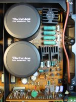
After I looked the bottom of the PCB, I saw a lot of bad solder joints.
Especially around the speaker output area. There is a dotterboard connecting the main PCB to the SPKR terminals. Every time I moved the wires or touched the output relays, the dotterboard, the distortion changed. To resolder all the solder joints I had to remove the output relays, which are soldered in to place.
The relays are also cleaned in the process. After the job, the amp is working fine. It didn't needed improvement, but a repair job. The large filter caps (18000uF) are also fine, replacing them would be difficult, because they are low profile kind , only 52mm tall. The hum level at 1kHz 3V out 8 Ohm is around -100dB.
Attachments

After I looked the bottom of the PCB, I saw a lot of bad solder joints.
Especially around the speaker output area.
There is a similar problem in old TV's where large connectors or connections get dry joints. SCART sockets are terrible for getting dry joints.
- Status
- Not open for further replies.
- Home
- Amplifiers
- Solid State
- Technics SE-9060 improvement?