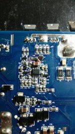
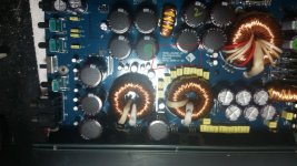
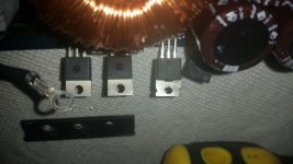
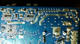
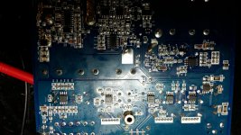
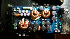
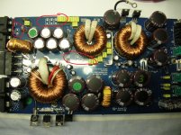
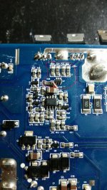
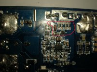
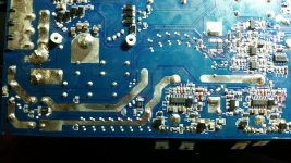
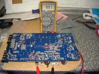
Hi, I have acquired one of these amps that needs repair. I have been reading through other threads and have noticed from the pictures posted that the underside of the board has a couple variations from what im seeing on mine.
1st thing im seeing is the resistors located at r136 and r137 only has one resistor at a 16 ohm value but then i noticed that further down the board at r135 or(138 cant tell) and r139 it is also missing one 16 ohm resistor. It appears to be a parallel configuration in series so i would think the value would offset the same with the exception of higher wattage capability .I was under the impression that this amp hasn't been worked on before and am at a personal debate of putting the two missing resistors into the circuit. So far all i have found on this amp was the power supply schematics and not the full print.
Also noticed that the power supply section has a variation located at the diode nzd1 on the posted photo. This leads me to believe there were different minor revisions of the R1000.1D.
This is the 1st car amp i decided to take a crack at but i am actually a Servo drive amp and VFD technician. After my long weekend is over i planed to take the amp to work and use my huntron tracker to go through the amp.
Oh yea the amp is flashing protect every few seconds with only power applied no rca and speakers hooked up. Also nothing looks burned or blasted.
Do you have a 35amp or better power supply? A volt/ohm meter?
Have you checked the output mosfets,Q104,Q105,Q106,Q107-IRFB3307 with an ohmmeter.
When you power up the amp what happens?Do you see the blue LED attempt to lit,or just the red LED flashing?
The more details the better.
Have you checked the output mosfets,Q104,Q105,Q106,Q107-IRFB3307 with an ohmmeter.
When you power up the amp what happens?Do you see the blue LED attempt to lit,or just the red LED flashing?
The more details the better.
Last edited:
Do you have a 35amp or better power supply? A volt/ohm meter?
Have you checked the output mosfets,Q104,Q105,Q106,Q107-IRFB3307 with an ohmmeter.
When you power up the amp what happens?Do you see the blue LED attempt to lit,or just the red LED flashing?
The more details the better.
No i dont have a 35 amp supply and it seems the in rush precharge on this amp is quite high.
I do manage to get the rail caps charged and get 70 volts with my 15 amp supply but the supply does drop voltage for a few seconds on 1st power up.
I have gone through the amp with my meter checking all surface resistors and Q104,Q105,Q106,Q107 look fine with the meter.
This amp is using IPP034NE7N in location q8 and q9 and not IRFB3077.
IPP034NE7N fets seems to be switching with 20 volts on the gate and meter on the drain and source readings.
I was stupid and thought D12 63ctq100 might be leaking suspect so i changed it out with a slightly lower rated component i had laying around and now blew out one of the 034ne7n fets in the supply. More then likely the dual diode in the supply was fine and i just introduced a new small issue to resolve.
So as of right now i am down a fet but still dont know why the amp is going into protect. It powers up in protect for a few seconds, flashes to blue for 2 seconds then repeats the cycle.
when blue i get 70 volt rail and 40 volt speaker reading from the ground to the drains of the two output fets.
I did check the amp directly on my truck battery to confirm that in wasnt just a small power supply issue. Also when replacing the two 16 ohm resistors into location from above it blew r140 27 ohm resistor.
Well being that i might be down for a few days waiting on parts i figured i would post a few photos of this amp with listed revision. I have seen some differences on the amp that might justify posting some new pictures with this earlier revision.
MODEL:R1000-1D
PN😛O86R10001
REV:A2
2009-11-06
Brief description of problem: Amp is powering up in protect mode for 5 seconds then goes blue and draws heavy current for a few seconds then returns to red protection for 10 seconds then blue for 2 seconds and repeats the loop. 10 red, 2 blue, .....
MODEL:R1000-1D
PN😛O86R10001
REV:A2
2009-11-06
Brief description of problem: Amp is powering up in protect mode for 5 seconds then goes blue and draws heavy current for a few seconds then returns to red protection for 10 seconds then blue for 2 seconds and repeats the loop. 10 red, 2 blue, .....
Just a small update
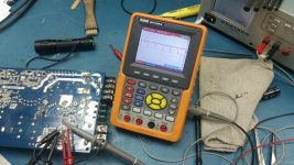
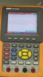
I got the supply fets in and got the amp to power up again and had some time to tinker. The amp is still broken flashing protect with nothing hooked up. Q1 has a good signature on the huntron but was replaced anyway. I did some checks on U1 pwm chip with the scope. v ref is 5 volts and output pin looks ok to me.
checked for correct voltage at Q110 then moved to u102 and u104 and checked for a square wave on pin 3
parts that i have in stock were replaced such the u101, u105. the pulse generator signatures match across all combinations of the output fets. all output fets are switching out of circuit. u102 and u104 are on order but both sides seem to be matching. This is my 1st car amp repair attempt but learning as i go.😛
Amp is flasing in and out of protect. readings above are what i could grab when the amp is in its brief blue light status. I think i might order some ZXTC2045E6 and re do the 4 of those but again.. they do look good with the huntron pulse generator signatures matching.
Judging from previous post the power supply is attempting to develop rails and the problem is most likely in the output or the protection circuit may be faulty.
This amp is very similar to the Kicker amps I work on, except that this amp uses a micro-controller for the protection circuit. I will need to study the schematic to see if there is a way to disable protection, there has to be a way.
In the meantime focus on the 2 output driver chips IRS20957 and 2045ES and surrounding circuitry. Quite often the these chips short internally, as well as the 2045's.
Also, the surface mount caps around the chips and outputs become leaky. Be sure check the gate resistors to the output mosfets.
The 27 ohm resistor burning up could mean there is oscillation in the output and may be the surface mount caps in the feedback circuit are faulty or the 16 ohm resistors you added may not be necessary and are causing oscillation. But as I said before I've never seen the zobel network have anything less then two 16 ohm resistors in parallel.
After I've had a chance to study the schematics I will post again.
I believe surface mount caps location c147 and c148 to not seem correct on the schematic. The schematic shows polarized 4.7uf 16 volt and this amp does not have polarized capacitors in that location. The .1uf in that locations matches the previous thread i was reading. i have found several differences like the input supply fets being IPP034NE7N and the resistors off of those fets are different values. Also i am noticing several differences in the amp revisions. Maybe those resistors dont go in that location? I honstly dont think the amp has had any previous person in it and it dont look like they fell off due to heat. But again this in my 1st car amp attempt. The amp output ic's are on order as well as the dual transistors.
Thanks for the reply and help.
Thanks for the reply and help.
Last edited:
Okay, you'll note on the schematics the RPO line (should be PRO for protection) to Pin 2 of U102 & U104-removing R503 & R110 may allow the amp to power up.
When you power up the amp monitor your current meter for excessive draw or the amp power supply mosfets for excessive heat and power down if need be. I think if the output protection is disabled you can safely power amp and check voltages and waveforms, that is the case with Kicker amplifiers with the same circuit topology.
If you've replaced the 27 ohm resistor and you have at least one 16 ohm resistor in each channel, they may burn up. If so, and if the 16 ohm on one channel burns up that would indicate a problem in the feedback circuit in that channel.
If the amp powers up safely, measure the DC voltage around U102,U104,U100,U101. If you can also look at the PWM, Pin 3 & Pin 13 of U102,104.
Replaced q100,q101,q102,q103,q104,u104,u102,q104,q105,q106,q107.
Same result, i get heavy current draw for a few seconds then flashing in and out of protect. removed 503, and r110 and the amp still goes into protect. checked voltage on diodes when blue i get 15 volts across d2,d3,d4,d5. I only see a spike of around 4 volts across d6, 8, 9, and 10. I get between 13 to 15 volts from positive to cathode on d6 and d10 and 13 to 15 volts from negative to anode on d9 and d8. I gotta admit im a bit frustrated at this point. I do get 40 volts from negative to speakers when in a blue state. 1st power up gets heavy current draw then amp draws around 2 amps when it attempts to come out of protect then goes right back into protect.
My last attempt i made to insert 16 ohm resistors on r138 and 136 blew the 27ohm resistor. and i would get a small chirp and heavy current draw when amp attempts to start up. Those resistors were not in the amp when i opened it up for the 1st time. all resistor values in output gating circuit measure correct. Also most of the parts i replaced looked correct on my pulse generator when i checked them but i was hoping the shotgun approach would have worked. Im starting to wonder if i have a capacitor issue or winding issue.
Last edited:
u101 was replaced and u105 were also replaced q1, and q7 were also replaced however u100 was not.
PapaZBill knows these amps much better than I do but the following may be helpful in troubleshooting.
Do you get rail-rail oscillation on both sets of output transistors?
When you power it up and it goes into protect, do you have greater heating on one pair of outputs than the other?
Before it goes into protect, do you have 40v on both positive and negative speaker terminals with very little DC offset between them.
I guess what it boils down to is my limited understanding of car amplifier circuitry. I have a scope at work where i repair servo amplifiers but at home i only have a meter with a pace desolder vacuum and iron.
q104 on one side and 106 on the other get 43volts from pin 2 to pins 1 and 3 when in protect and 30 when not in protect.
q105 and 107 get 26 volts from pin 2 to pins 1 and 3 when in protect and 40 when not in protect.
both positive and negative speaker terminals are within 0.2 volts around 39.8 to 40 from what i can tell.
Thanks for the reply.
Check between U2-Pin5(MCU) and U101-Pin's 3 & 5-LM393 for continuity. The schematic indicates there may be a D19-0 ohm resistor/jumper connecting these two points. Lifting D19 may disable protection.
Whether or not this is the case, look at the PWM on U101 Pins 3 & 5 and check for a sawtooth waveform. If there is none, check U105 Pin 3 & 5 for 12 Vdc. If this voltage is low or non existent, check for a shorted ZD102 or a leaky cap across ZD102 & ZD105. These two diodes along with ZD3 form a voltage ladder-12v,24v & 12v respectively.
The other possibility is U105 is not oscillating which may be a leaky or cracked C114 & or C115-471 sm caps. Or a distorted sawtooth caused by C141 or C136.
I wish I knew a more definitive way to disable protection. If nothing else lifting pin 5(D2) and/or pin 7(D3) of U2 may disable protection.
Hang in there,nothing worth doing is ever easy. Whether working with servo amplifiers or car amplifiers the principles of electronics are basically the same, we are dealing with controlling a motor in one form or another.
- Status
- Not open for further replies.
- Home
- General Interest
- Car Audio
- Rockford Fosgate R1000-1D protect issue.

