I'm building a tube preamp. The pcb has a 12vdc tap to use for an on/off led indicator - works fine. However, I thought it would look cool (but not necessary) to install a matching led to indicate whether the tape monitor circuit was engaged.
I've got a couple of switches on hand, both on/on - both two pole, one is one throw, the other is two throw (on-off-on). Naturally, all the current passing through the switch is audio signal (low voltage, a/c).
Is there a way to do this?
I've got a couple of switches on hand, both on/on - both two pole, one is one throw, the other is two throw (on-off-on). Naturally, all the current passing through the switch is audio signal (low voltage, a/c).
Is there a way to do this?
You would need a spare and unused set of contacts on the tape monitor switch to feed the LED through. If they are all taken for audio then it can't be done.
You would need a spare and unused set of contacts on the tape monitor switch
to feed the LED through. If they are all taken for audio then it can't be done.
There are 4PDT switches in most styles.
http://www.ebay.com/itm/like/301427366793?lpid=82&chn=ps&ul_noapp=true
Last edited:
Switches are always confusing to me; I'll dig up a schematic on a 4P2T and see if that seems logical and safe: I wouldn't want the possibility of sending 12vdc to the signal attenuator.
Thanks for the advice, likely I'll be back with more questions.
Thanks for the advice, likely I'll be back with more questions.
You need a spare set of contacts.
If in doubt, then just measure the resistance from all of your proposed pins that you intend to use for the LED on the switch, to those used for the audio. There should be no continuity with the switch in all its positions.
If in doubt, then just measure the resistance from all of your proposed pins that you intend to use for the LED on the switch, to those used for the audio. There should be no continuity with the switch in all its positions.
Switches are always confusing to me; I'll dig up a schematic on a 4P2T and see if that seems logical and safe:
A 4PDT is like two of what you have now, ganged together to act as one mechanically.
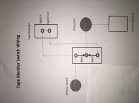
Here's a diagram I made to wire the tape monitor switch. The switches that I would use are 3 pole and one or two throw - either would work, 1 throw is better.
If you guys tell me that a four pole switch would work and also switch a dc led current, without risking dumping that dc into the signal, then I'll get one and experiment until I understand how to set it up.
Guess ther could be two sources for dc corruption: first proximity of dc and ac in the same switch and second switching dc voltage directly into the ac signal, I'm concerned about the second possibility.
Sorry I'm so thick.
Thanks again
Attachments
Last edited:
OK, I can see what you are trying to do there. Yes, a four pole double throw as Rayma suggested would give you spare contacts to wire an LED to.
So you are feeding the selected audio source to the tape deck and simple using the switch to select either 'source' or 'monitor'.
So you are feeding the selected audio source to the tape deck and simple using the switch to select either 'source' or 'monitor'.
OK, I can see what you are trying to do there. Yes, a four pole double throw as Rayma suggested would give you spare contacts to wire an LED to.
So you are feeding the selected audio source to the tape deck and simple using the switch to select either 'source' or 'monitor'.
Yes. The signal travels from the source directly to the attenuator, or passes through the tape recorder and then to the attenuator. That's the recommended method for my project, and, from what I can learn, the traditional way to wire a tape monitor switch.
If you guys tell me that a four pole switch would work and also switch a dc led current,
without risking dumping that dc into the signal, then I'll get one and experiment until I
understand how to set it up. Guess ther could be two sources for dc corruption: first
proximity of dc and ac in the same switch and second switching dc voltage directly into the ac signal.
If the switch is rated at 250VAC/32VDC like most are, then there's no chance of any problems.
The DC can't induce noise into the signal, since it does not vary.
Now draw a complete schematic showing all connections to each switch terminal.
A very minor point you might encounter. If the board has a '12 volt feed' that is designed to run an LED directly (in other words it has a series resistor on the board), then you won't be able to add another LED directly to that feed. You would need to duplicate it by creating a separate feed that has its own resistor, fed from the same source on the board.
If you have a circuit for the LED feed on the preamp then we can tell you the best way to arrange it.
If you have a circuit for the LED feed on the preamp then we can tell you the best way to arrange it.
You're right about that. The existing 12 vdc lead requires a resistor to prevent the led from burning out.
OK, if the outlet on the board is a true 12 volt source (no resistor... you add that to the LED) then you should be able to use that outlet to feed another LED + resistor.
Hope that makes sense.
Hope that makes sense.
Couldn't find anything locally, so I ordered a switch from Amazon. Just got here. It's labeled 4PDT - 2 positions latching. It has four columns of three pins. Each 3 pin row is an on-on switch. The switch handles 4 unrelated circuits. That would work for what I need. In fact, I really only need two circuits. This is what everybody has been trying to explain.
Now I get it! Duh.
I'm going to have to order a better quality switch for my build. What I need is a switch with two separate, 3 pin, on-on circuits. Would that be called DPDT?
Now I get it! Duh.
I'm going to have to order a better quality switch for my build. What I need is a switch with two separate, 3 pin, on-on circuits. Would that be called DPDT?
Just corrected myself. Need 3 circuits: two audio channel circuits, one led circuit.
3PDT. (or 4PDT)
3PDT. (or 4PDT)
- Status
- Not open for further replies.
- Home
- Design & Build
- Construction Tips
- Wiring a tape monitor led