Hi all.
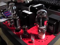
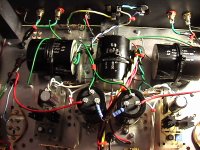
Building the JC Morrison 300B SET with some of the great mods done by Stamiou including the DC filament supply. It's coming along well, see pics. Want to monitor the 300B current with two 100ma alalogue meters but not sure where to insert them.
1. Between pin 2 and the OPT
2. Between cathode tail and ground or
3. Somewhere else.
Any help from more experienced members much appreciated.
Particularly discussion on cathode vs anode current.
When done I would like to share the build here if of interest.
tks and regards
Dave.
Attachments
Usually I connect the current meter between the cathode and the ground if fixed bias or cathode load resistor and ground if biased with 0v on the grids.
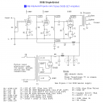
There are four possibilities to connect mA-meter.
1. At +Ub rail just before the opt.
2. Between opt and anode of 300B
3. At the top end of R6
4. At the bottom end of R6
The lay-out / wiring determines what is the best choice.
1. At +Ub rail just before the opt.
2. Between opt and anode of 300B
3. At the top end of R6
4. At the bottom end of R6
The lay-out / wiring determines what is the best choice.
Put a 1ohm 2w after the R6/C4 to ground and take a test point or millivoltmeter you can read directly the mA
Walter
Walter
I wouldn't want a meter connected permanently in series with the output tube. I think the best solution is a 1r or 10r resistor in series with R6 between R6 and ground. Use a voltmeter to monitor current.
...Want to monitor the 300B current with two 100ma alalogue meters...
I agree, but above is what op asked, not how to use volt meters.
If it is a 100mA meter, no shunt is needed.Best put diodes across to protect them.Hi all.
Building the JC Morrison 300B SET with some of the great mods done by Stamiou including the DC filament supply. It's coming along well, see pics. Want to monitor the 300B current with two 100ma alalogue meters but not sure where to insert them.
1. Between pin 2 and the OPT
2. Between cathode tail and ground or
3. Somewhere else.
Any help from more experienced members much appreciated.
Particularly discussion on cathode vs anode current.
When done I would like to share the build here if of interest.
tks and regards
Dave.
I would put those there.
Mona
Attachments
Thank you for all the replies. I have gone with Ketje's solution as I want it permanent and safe.
I though small amp meters of good quality would be the go. Link is here: 2pcs 45mm Round Moving Coil Panel Meter DC100MA FOR 2A3 300B 6550 211 KT88 AMP | eBay
Been buying from these guys for years and they are very good for all tube amp supplies
thanks again
Dave.
I though small amp meters of good quality would be the go. Link is here: 2pcs 45mm Round Moving Coil Panel Meter DC100MA FOR 2A3 300B 6550 211 KT88 AMP | eBay
Been buying from these guys for years and they are very good for all tube amp supplies
thanks again
Dave.
Hi again to all.
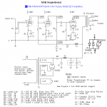
Having said this project was coming along nicely I have now run into a B+ problem I can't solve. The circuit is a little different to the original one posted earlier here as I didn't want to have separate rectifiers for each channel.
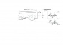
The B+ supply is pretty standard as far as I can see. But in this case all is well only until you plug in even one of the JJ 300B's.
Then the B+ peaks at about 520V for a second as usual then settles down to the required 450 volts at C4 or C5 on the attached. But only for a second or two. Then it gradually decreases over a minute or so to under 250V. Where I stopped it not wanting to break anything.
Have tried 3 different rectifiers EH, JAN Philips and RCA. As well as checking the circuit again including grounds. Same result. The current requirement seems well within what is available. I was going to take some current measurements but would rather not if possible. A little scary at this voltage.
Hoping again some more experienced member can point me in the right direction.
thanks and regards
Dave.
Having said this project was coming along nicely I have now run into a B+ problem I can't solve. The circuit is a little different to the original one posted earlier here as I didn't want to have separate rectifiers for each channel.
The B+ supply is pretty standard as far as I can see. But in this case all is well only until you plug in even one of the JJ 300B's.
Then the B+ peaks at about 520V for a second as usual then settles down to the required 450 volts at C4 or C5 on the attached. But only for a second or two. Then it gradually decreases over a minute or so to under 250V. Where I stopped it not wanting to break anything.
Have tried 3 different rectifiers EH, JAN Philips and RCA. As well as checking the circuit again including grounds. Same result. The current requirement seems well within what is available. I was going to take some current measurements but would rather not if possible. A little scary at this voltage.
Hoping again some more experienced member can point me in the right direction.
thanks and regards
Dave.
Attachments
First step is to isolate the problem to either PSU or amplifier. You could use something like a 5K 50W dummy load resistor to test the PSU, but maybe those cathode current meters will tell the story. Does the pointer go against the peg as supply voltage caves?
Thanks BinaryMike. Wired up one channel with the meter as per Ketje's circuit. Same voltage behaviour and the meter stays at zero. So I placed an Ma meter at the output of the 5H choke. Same result zero current. Never seen anything like this before. Any advice appreciated. Dave.
So, the voltage drops with no current ? Rectifier tube ok ? is the heater glowing ? Fuse good contact ?
Mona
Mona
Check DC voltage upstream, across L1 and R1, and then AC voltage at rectifier anodes. Take care -- keep one hand in pocket.
So, the voltage drops with no current ? Rectifier tube ok ? is the heater glowing ? Fuse good contact ?
Mona
Yes the rectifier is on a gets hot. Fuses checked and seem good. See next reply for some voltages and more info.
Check DC voltage upstream, across L1 and R1, and then AC voltage at rectifier anodes. Take care -- keep one hand in pocket.
Thanks BinaryMike. I keep both my hands in pockets with this stuff. Have built many of these designs at around 600 VAC this is the first at 800 with a 5U4GB. Maybe somewhere is getting to ground and the decaying B+ is just the caps discharging. That would break a fuse surely. Thought the rectifier tube the obvious suspect. But 3 have been tried with same results. All connections have been checked times over.
Using a variac to set primary voltage exactly, following are the results.
1. Across both R1 and L1 about 3 VDC and slowly rising when B+ is still falling.
2. Across rectifier anodes 789 VAC steady within 2 volts.
3. Across rectifier filament 4.96 VAC steady.
4. Also shorted out the 800V CT fuse to check holder with same results.
Transformer is a brand new Hammond 378X as attached.
thanks for your help. Dave.
Attachments
3VDC across 75R is 40mA, which is high for the 6SN7s by themselves, but they're probably seeing more supply voltage than intended. 40mA is way lower than I would expect if you had a short to ground on the B+ line. This makes me wonder about your 5U4s again. Could you sub the tube by clipping in a couple of 1N4007 diodes in series to R1 at each end of the 800V winding and bring line voltage up to about 110V as a test?
Sorry, I should have said these tests were done with all tubes inserted. To get to a real operating condition. Even though just one 300B in does the same. Make a difference?
Well, 40mA isn't going to do any damage even if it's all going through a single 300B. Unless you have some independent way to rule out failed 5U4s, or a separate benchtop PSU, then I still think SS rectifier substitution is a good way to proceed with troubleshooting. It's a very simple and quick test if you use clip leads.
Well, 40mA isn't going to do any damage even if it's all going through a single 300B. Unless you have some independent way to rule out failed 5U4s, or a separate benchtop PSU, then I still think SS rectifier substitution is a good way to proceed with troubleshooting. It's a very simple and quick test if you use clip leads.
What a great idea! Used what I had 1N5408's and with 2 each 6SN7 and 300B inserted here are the results.
1. Line in at half normal 120 VAC the B+ out is 274V and steady.
2. Increasing line in until 300B plate voltage is 430 stays steady for maybe 5 seconds and then slowly decays but has a few goes at increasing by a few volts on the way down.
What next? I am currently upgrading my tube tester to test DHT's. Or maybe that first 39uF Solen cap is faulty. They have some reputation in that regard although I have never had any issues with them. And had a 47uF Solen in there as per original design to start and saw the same problem.
tks Dave.
- Status
- Not open for further replies.
- Home
- Amplifiers
- Tubes / Valves
- Morrison 300B SET - where to connect current meters?