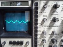
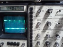
Got a Kicker KX1200.1 amp. Amp coming on but no output. Replaced 240 ohm resistors R195, 155, 204 & 215. Replaced 180 ohm resistors R193, 194, & 169. Replaced 2K resistor R201. Replaced 1K resistor R274. Replaced Diode D118. Amp would power up and immediately go into protect. Replaced U14 NE529 voltage comparator. Amp powers up and plays good at low power output. When I crank it to about 50 watts this is what I get. It doesn't pull the power supply down. Any ideas?
Attachments
![20160622_161305[1].jpg](/community/data/attachments/505/505659-dd18a32fc0da6d44ef24187ccef470bd.jpg?hash=3RijL8DabU)
BTW, the scope is grounded to the -speaker out. The probe is on the +speaker out in this picture.
What is the DC voltage across pins 10 and 14 of U14?
Is the output on pin 11 of U14 swinging to within a few millivolts of the voltage on pins 10 and 14?
Is the output on pin 11 of U14 swinging to within a few millivolts of the voltage on pins 10 and 14?
Negative probe on pin 10, positive probe on pin 14, reading +5 volts
Negative probe to - speaker, positive probe to pin 11, reading +.5 volts
Negative probe on pin 11, positive probe on pin 10, reading -2.5 volts
Negative probe on pin 11, positive probe on pin 14, reading +2.5 volts
Negative probe to - speaker, positive probe to pin 11, reading +.5 volts
Negative probe on pin 11, positive probe on pin 10, reading -2.5 volts
Negative probe on pin 11, positive probe on pin 14, reading +2.5 volts
You would have to use your scope to see if the output from pin 11 is swinging to the voltages on pins 10 and 14.
The 5v across 10 and 14 is good.
If U14 isn't swinging quite far enough towards pin 10, it can cause the distortion. It could also be due to out of tolerance resistors, defective drivers, etc.
PapaZBill can probably get you through the repair quicker. I'm simply checking the simplest things.
The 5v across 10 and 14 is good.
If U14 isn't swinging quite far enough towards pin 10, it can cause the distortion. It could also be due to out of tolerance resistors, defective drivers, etc.
PapaZBill can probably get you through the repair quicker. I'm simply checking the simplest things.
I think the problem is on the input pin 3. I can monitor the noise on that pin. Can you tell where the signal for that input originates? I have a diagram of a KX1200.1 but is not of this board.
Pin 3 is inside the feedback loop. When the servo/feedback circuit senses that there is distortion, it drives its output as hard as necessary to eliminate the distortion. That's likely what you're seeing if you're seeing a spike that corresponds to the clipped portion of the output. You can align them by using two channels of your scope to confirm that they coincide.
Pin 10 is set at -2 Vdc, Pin 14 is set at 3 Vdc, hence the 5 Vdc across them, which as Perry mentioned is good.
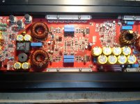
Post a picture of board? That will help me determine which version you have.
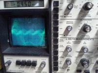
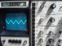
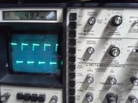
Using your scope, look at Pins 3,4 and 11 and post a screen shot if you can.
There are four 12 volt zeners, one for each drive circuit, D107,108,120,121. Check across each one.
Post a picture of board? That will help me determine which version you have.
Using your scope, look at Pins 3,4 and 11 and post a screen shot if you can.
There are four 12 volt zeners, one for each drive circuit, D107,108,120,121. Check across each one.
Thanks PapaZBill, I can post all that for you tomorrow. I have to take care of my wife right now. She is in bad health.
Pin 10 is set at -2 Vdc, Pin 14 is set at 3 Vdc, hence the 5 Vdc across them, which as Perry mentioned is good. ( This is correct)
Post a picture of board? That will help me determine which version you have. (Posted)
Using your scope, look at Pins 3,4 and 11 and post a screen shot if you can. (Posted showing pin 3 signal down and up, Pin 11 showing signal down and up.)
There are four 12 volt zeners, one for each drive circuit, D107,108,120,121. Check across each one. (Checked across each zener. Reading 12.3 volts)
Attachments
Sorry for delay,other projects have me occupied.I'll get back to you later today.
Sent from my HTC Desire 626 using Tapatalk
Sent from my HTC Desire 626 using Tapatalk
No problem. I know all about having projects that keep you occupied. Look foreword to your help when you can.
I reread your #1 post and realized the values you stated for R155,R215 are wrong, and should be 120 ohm's. My apologizes for not catching this sooner.Also, R195,204 should be 220 ohm's.
Was this a typo or in fact the values you used? This could account for the distortion.
I don't know if 20 ohms would make a difference but, I would recommend changing the R195,204 to 220 ohm, as well as R155,215 to 120 ohm.
Was this a typo or in fact the values you used? This could account for the distortion.
I don't know if 20 ohms would make a difference but, I would recommend changing the R195,204 to 220 ohm, as well as R155,215 to 120 ohm.
Thanks PapaZBill, I could read the value on R204 as 241 (240ohm). All four groups of resistors looked the same so I assumed R155 and 215 would be the same value. My mistake. Changed to 120 ohms and the amp is running correctly now. I don't have a diagram on this version so I couldn't check the value. Correct resistors and U14 repaired the unit. Thanks again to you and Perry for the help.
- Status
- Not open for further replies.
- Home
- General Interest
- Car Audio
- Kicker KX1200.1 Distorted output