First, please forgive what I'm sure is an elementary question, but it really has me stumped. What I thought would be a fairly straightforward task has made me realize that I'm in over my head.
I'm in the process of building a passive preamp that will connect to the RCA inputs of this amp board:
http://www.parts-express.com/pedocs...aS5630-class-d-amplifier-board-new-manual.pdf
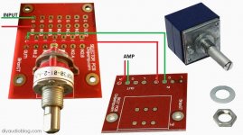
I'm using a Grayhill selector switch and Alps volume pot that I purchased from chipamp.com. They are the parts pictured here:

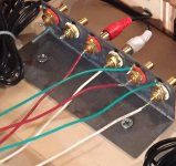
I have connected the ground and signal wires from my RCA jacks to the ground points and inputs on the selector PCB. From there I have connected the two outputs of the selector PCB to the inputs of the volume pot PCB.
Then I cut one end of an RCA cable and soldered those to the left and right outputs of the volume pot. I used the shielding wire of the RCA cable to attach to the ground points on the volume pot PCB on the output side.
The end result is that I'm only getting sound from one channel. I can switch the RCA connections on the amp and sound will come out of the other side, so I know that the problem is with either my selector switch or volume pot. I'm just not sure which or how to fix it.
Since I couldn't find much documentation that showed exactly what the wiring should look like, I was hoping someone here might be able to tell me if I'm missing something.
Thank you in advance for any advice that you can offer.
I'm in the process of building a passive preamp that will connect to the RCA inputs of this amp board:
http://www.parts-express.com/pedocs...aS5630-class-d-amplifier-board-new-manual.pdf
I'm using a Grayhill selector switch and Alps volume pot that I purchased from chipamp.com. They are the parts pictured here:
I have connected the ground and signal wires from my RCA jacks to the ground points and inputs on the selector PCB. From there I have connected the two outputs of the selector PCB to the inputs of the volume pot PCB.
Then I cut one end of an RCA cable and soldered those to the left and right outputs of the volume pot. I used the shielding wire of the RCA cable to attach to the ground points on the volume pot PCB on the output side.
The end result is that I'm only getting sound from one channel. I can switch the RCA connections on the amp and sound will come out of the other side, so I know that the problem is with either my selector switch or volume pot. I'm just not sure which or how to fix it.
Since I couldn't find much documentation that showed exactly what the wiring should look like, I was hoping someone here might be able to tell me if I'm missing something.
Thank you in advance for any advice that you can offer.
Attachments
If you have a simple VOM, check from the output terminals to the input(s) if there are continuity at both channels, and that the resistance measured be equal between them. Also check output resistance to ground, perhaps a tiny jumper of tin shortcircuited one output.
But, a preamplifier must be active, if no active element(s) (Say, tube transistor, FET or opamp), then there is no amplification and no preamp at all, simply a passive equalizer only.
But, a preamplifier must be active, if no active element(s) (Say, tube transistor, FET or opamp), then there is no amplification and no preamp at all, simply a passive equalizer only.
If you have a simple VOM, check from the output terminals to the input(s) if there are continuity at both channels, and that the resistance measured be equal between them. Also check output resistance to ground, perhaps a tiny jumper of tin shortcircuited one output.
But, a preamplifier must be active, if no active element(s) (Say, tube transistor, FET or opamp), then there is no amplification and no preamp at all, simply a passive equalizer only.
Thanks for your response. I figured I was using terminology wrong!
Since the amp board that I'm using doesn't have multiple inputs, my goal was to add the input selector and volume pot to allow for multiple sources. Being so new to all of this, I assumed that was what a passive preamp was. My apologies.
I will try to check the continuity and resistance between the output and input terminals tonight. I assumed that I was missing something in the way that I had things wired, but it sounds like that might not be the case.
Thanks again.
Thanks for your response. I figured I was using terminology wrong!
...
My apologies.
Don't worry, only a brief explanation.
I forgot to mention that the method above described, will fail if there is a capacitor in series with the signal, as I haven't the schematic of your PCB under question.
Keep posted about progress.
Good luck‼
a preamplifier must be active, if no active element(s) (Say, tube transistor, FET or opamp),
then there is no amplification and no preamp at all, simply a passive equalizer only.
Passive preamplifier has been the standard term used for a long time now.
May be a colloquial terminology, but not technical one, IMHO.
As Engineer, I prefer technical words.
As Engineer, I prefer technical words.
Actually, try - Attenuator -
Back to the issue....
I think we need to see pics of the entire construction.
Sounds like a wiring issue.
Back to the issue....
I think we need to see pics of the entire construction.
Sounds like a wiring issue.
Do you have signal return (also known as 'ground') continuity from input though selector and volume PCBs to output?jwmatx said:I have connected the ground and signal wires from my RCA jacks to the ground points and inputs on the selector PCB. From there I have connected the two outputs of the selector PCB to the inputs of the volume pot PCB.
How to wire a selector switch and a volume pot are all over the net. You need to look a little harder.Since I couldn't find much documentation that showed exactly what the wiring should look like, I was hoping someone here might be able to tell me if I'm missing something.
Yes.You look to be lacking two ground wires on the rca connectors
Each and every input must be connected with two wires.
Those two wires must be close coupled and preferably coaxial, or twisted.
The two wires are signal flow/hot and signal return/cold.
The hot goes to the swtiched terminal.
The cold goes to the common terminal. It is NOT ground. It is the signal return terminal.
The switch output also has a two wire connection.
Signal hot goes to the input of the attenuator.
Signal cold (common) goes to the return/common terminal of the attenuator. It is opposite to it's input.
The attenuator has a two wire connection coming in and also has a two wire connection going out.
The output hot is from the wiper (the middle terminal).
The output cold is from the common/return terminal.
Yes.
Each and every input must be connected with two wires.
Those two wires must be close coupled and preferably coaxial, or twisted.
The two wires are signal flow/hot and signal return/cold.
The hot goes to the swtiched terminal.
The cold goes to the common terminal. It is NOT ground. It is the signal return terminal.
The switch output also has a two wire connection.
Signal hot goes to the input of the attenuator.
Signal cold (common) goes to the return/common terminal of the attenuator. It is opposite to it's input.
The attenuator has a two wire connection coming in and also has a two wire connection going out.
The output hot is from the wiper (the middle terminal).
The output cold is from the common/return terminal.
I understand that every input has to have two wires. One is signal flow/hot and the other is signal return/cold.
What I don't understand is how I am going to get continuity on the returns all the way from the rca inputs, through the input switch, through the volume pot and to the rca inputs on my amp board.
I know you said that the return is NOT ground, but my understanding was that the return from each input should go to the pads marked "G" on the input switch PCB. I understood these to be "ground". They are in no way connected to the "G" pads on the outputs of the switch. So it would seem that my continuity would end there.
And that's where it breaks down for me. What am I missing?
Thank you for taking the time to explain this to me. I'm just having a hard time picturing how I can accomplish what you've described.
Normally the input returns are connected directly to the output returns and other "common"
(sometimes incorrectly called ground) parts of the circuit. It may be that your pcb does not
provide this common connection. Then you would have to make the connection externally,
outside of the pcb, for proper circuit functioning. Do you have a schematic?
Sorry, I don't have a schematic, just the details (and photos) that I included in my original post.
So, would it be ok to take the input returns and connect them directly to the output returns of my volume pot, bypassing the input switch PCB completely?
would it be ok to take the input returns and connect them directly to the output returns
of my volume pot, bypassing the input switch PCB completely?
I don't see why not, if you keep the channels correct and don't accidentally switch them.
In rare circuits, the input commons are switched along with the hot leads,
but not in this case, so the common connections can be made externally to the board.
Be careful when trying this, use either a junk speaker or run the passive output
into a regular preamp with its own volume control, just for testing.
If everything isn't right, you could get a loud hum or buzzing sound.
Last edited:
Consider each link as starting with a SOURCE and finishing with a RECEIVER. Ignore everything beyond Source-link-Receiver..............What I don't understand is how I am going to get continuity on the returns all the way from the rca inputs, through the input switch, through the volume pot and to the rca inputs on my amp board.
The Source has two outputs: the flow/hot and the Return/cold. The Receiver has two inputs: the flow/hot and the Return/cold.
Connect the source signal hot to the receiver signal hot. Connect the source signal cold to the receiver signal cold. Those two wires need to be close coupled along the whole route of the link.
repeat for EVERY Source to Receiver.
the G at the amp PCB input is probably the Signal Cold/Return. But the use of the ground word is so ingrained that even professionals misuse it repeatedly. The G may be connected internally on the PCB to the Power ground and Speaker return. The amplifier needs to set the output with reference to the input signal. It does this with that internal voltage reference connection.I know you said that the return is NOT ground, but my understanding was that the return from each input should go to the pads marked "G" on the input switch PCB. I understood these to be "ground". They are in no way connected to the "G" pads on the outputs of the switch. So it would seem that my continuity would end there.
Complete the module to module links with two wire connections.And that's where it breaks down for me. What am I missing?............
There is one exception.
A dual polarity PSU feeding power to a dual polarity Amplifier. This uses a twisted triplet with three wires that are close coupled and twisted. The three wires are +ve feed, -ve feed and PSU Zero Volts.
The problem is we don't understand how you can fail to get continuity if you wire it through correctly. Your inputs, outputs and volume control must have return connection points. The input switch may not, so if not you simply connect the input returns to the volume returns point.jwmatx said:What I don't understand is how I am going to get continuity on the returns all the way from the rca inputs, through the input switch, through the volume pot and to the rca inputs on my amp board.
Draw a diagram of how you think you should connect it. A diagram is much better than a description, and often better than a photograph. That may help us see what it is that you can't see.
Originally Posted by jwmatx
............."What I don't understand is how I am going to get continuity on the returns all the way from the rca inputs, through the input switch, through the volume pot and to the rca inputs on my amp board."
Well done ! It is thinking of connections as not being made or being too long and therefore vague, that gives you proper insight into their over complexity, and moving
forward - very good reason to find more elegant solutions.
Cheers / Chris
The boards both use ground planes where all the grounds (left/right/in/out) are connected together. In G connects to Out G though the ground plane. If you have made good connections then you should measure near zero Ohm between RCA input ground and RCA amp input ground.
The same can be done for the supply leads. Set the selector switch to the correct channel and the pot to full volume and you should also measure zero volts.
The same can be done for the supply leads. Set the selector switch to the correct channel and the pot to full volume and you should also measure zero volts.
Attachments
- Status
- Not open for further replies.
- Home
- Source & Line
- Analog Line Level
- Preamp problem