The old and the new...
Here's a snap of a couple of Ales's regulator boards that I'm using to power a JLSounds USB board in a 'No-DAC' DSD project.
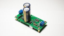
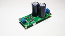
The white board is an early version of Ales's regulator boards and will power the USB input section of the JLSounds board. The green board is the latest version, with CLC pre-filter, and will power the reclocking section where it's lower noise should pay dividends.
Each board is supplied by a 6VAC secondary and I've measured the voltage at the power connections of the JLSounds at 5.02 and 5.03volts so bang on.
Good stuff Ales.
Cheers
Ray
Here's a snap of a couple of Ales's regulator boards that I'm using to power a JLSounds USB board in a 'No-DAC' DSD project.
An externally hosted image should be here but it was not working when we last tested it.
The white board is an early version of Ales's regulator boards and will power the USB input section of the JLSounds board. The green board is the latest version, with CLC pre-filter, and will power the reclocking section where it's lower noise should pay dividends.
Each board is supplied by a 6VAC secondary and I've measured the voltage at the power connections of the JLSounds at 5.02 and 5.03volts so bang on.
Good stuff Ales.
Cheers
Ray
Thank you for sharing this. How many VA per 6VAC channel? How much current does each section need?
Thank you for sharing this. How many VA per 6VAC channel? How much current does each section need?
Both secondary windings are 6VAC @ 1.25A
USB input section requires 5VDC @ 450mA, reclocker requires 5VDC @ 250mA (see the JLSounds I2SoverUSB product documentation).
Just got mine but it did not come with heat sink. Is it necessary to get one?
It really depends on difference between input and output voltage of the regulator and load current.
BR,
Aleš
TPS7A4700 LNPSU
After long delay here is new TPS7A4700 PCB.
New features:
Low voltage drop rectifying schotkky diodes
Input CLC filter with 2x 4700uF Panasonic FC and ACM7060 common mode choke filter
3x 22uF capacitors on the output, additional small value capacitor can be placed over C8 to define the sound
LC output filter (for relaxing the harshness of regulator), can omitted with solder jumper SJO!
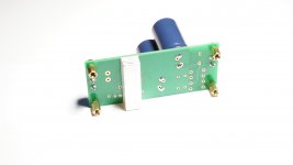
Voltage can be set with solder jumpers or Omron dip switch
Buying options
Single LNPSU assembled and tested
Price = 28€
Dual LNPSU assembled and tested
Price = 56€
Single LNPSU partially assembled and tested kit
Price = 25€
Kit also includes:
2x 4700uF Panasonic FC
4x standoffs + M3 nuts
2x PCB screw terminal
1x aluminum heatbridge
Omron DIP switch is NOT included!
Dual LNPSU partially assembled and tested kit
Price = 50€
Kit also includes:
4x 4700uF Panasonic FC
8x standoffs + M3 nuts
4x PCB screw terminal
2x aluminum heatbridge
Omron DIP switch is NOT included!
Shipping
All packages will be shipped with tracking number.
Shipping rates are:
up to 100g: 4€ (1unit)
up to 250g: 5.22€ (up to 4units)
up to 500g: 6.99€ (more than 4units)
1unit = 1x single LNPSU
2units = 1x dual LNPSU
Please send PM for inquiry!
Pictures represent single assembled LNPSU!
After long delay here is new TPS7A4700 PCB.
New features:
Low voltage drop rectifying schotkky diodes
Input CLC filter with 2x 4700uF Panasonic FC and ACM7060 common mode choke filter
3x 22uF capacitors on the output, additional small value capacitor can be placed over C8 to define the sound
LC output filter (for relaxing the harshness of regulator), can omitted with solder jumper SJO!
Voltage can be set with solder jumpers or Omron dip switch
Buying options
Single LNPSU assembled and tested
Price = 28€
Dual LNPSU assembled and tested
Price = 56€
Single LNPSU partially assembled and tested kit
Price = 25€
Kit also includes:
2x 4700uF Panasonic FC
4x standoffs + M3 nuts
2x PCB screw terminal
1x aluminum heatbridge
Omron DIP switch is NOT included!
Dual LNPSU partially assembled and tested kit
Price = 50€
Kit also includes:
4x 4700uF Panasonic FC
8x standoffs + M3 nuts
4x PCB screw terminal
2x aluminum heatbridge
Omron DIP switch is NOT included!
Shipping
All packages will be shipped with tracking number.
Shipping rates are:
up to 100g: 4€ (1unit)
up to 250g: 5.22€ (up to 4units)
up to 500g: 6.99€ (more than 4units)
1unit = 1x single LNPSU
2units = 1x dual LNPSU
Please send PM for inquiry!
Pictures represent single assembled LNPSU!
Attachments
Which is the cost for omron dip switches?
I am using A6H-8101 and I can guarantee this model fits the board.A6H-8101 - OMRON ELECTRONIC COMPONENTS - DIP / SIP Switch, A6H Series, SPST, SMD, 8 Circuits, DIP Unsealed, 24 VDC | Farnell element14.
I haven't tried any other model but I think you'll find cheaper options on the link below:
| Farnell element14
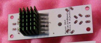
If I get heat sink myself, where is the exact location to put it on?
You can place it between the two white lines on the bottom of the PCB. 10mm x 35mm will fit the board perfectly.
Best regards,
Aleš
Hi Aleš, I already have your older board, soon to be used as a 5V pre-regulator to a reclocker board, which has an onboard 3.3V ADM7151 regulator.
If I was to use your new board instead, 2 questions:
i) are the new filters/chokes an advantage in my situation, in terms of blocking noise from the AC line?
ii) since my reclocker board will draw no more than 150mA @ 5V, is it OK to use the old-style 20x14 heatsink, or should I still use your heatbridge-to-chassis ?
Attachments
Hi Aleš, I already have your older board, soon to be used as a 5V pre-regulator to a reclocker board, which has an onboard 3.3V ADM7151 regulator.
If I was to use your new board instead, 2 questions:
i) are the new filters/chokes an advantage in my situation, in terms of blocking noise from the AC line?
ii) since my reclocker board will draw no more than 150mA @ 5V, is it OK to use the old-style 20x14 heatsink, or should I still use your heatbridge-to-chassis ?
Hi linuxfan,
i) Since you'll be using TPS7A47 PCB as preregulator, new board with filters will not bring any significant overall improvements.
ii) Yes, the old style heatsink will be OK, just make sure AC input voltage will not be very high. Try to source 6v AC transformer.
Best Regards,
Aleš
Thanks.
I'm still interested to know the purpose/benefits of this filter-choke regime. It appears to be in-vogue at the moment, particularly on a certain Hong Kong website.
I'm still interested to know the purpose/benefits of this filter-choke regime. It appears to be in-vogue at the moment, particularly on a certain Hong Kong website.
Years ago we started using them for RF filtering on a PSU and also a DAC (both coils and common mode coils). "What can't come in can't disturb anything". This was very easy proven with some simple experiments and measurements. I choose ACM7060 and ACM1211 series as they have very low DC resistance so low loss and still very good RF filtering. Coils were definitely not in vogue then, due to their cost. Now they are in vogue again and to my surprise their price is way lower than some years ago too. ACM1211 was 7 Euro then and costs 2.38 Euro today despite high copper prices. Cost is not an objection anymore, their benefits are quite clear and they don't cause harm so it is only a good thing they are back from the past ! 😉
I also use them at outputs of regulators (with care !) to avoid feedthrough from the device to its PSU. A nice touch don't you think ?
I also use them at outputs of regulators (with care !) to avoid feedthrough from the device to its PSU. A nice touch don't you think ?
Last edited:
I also use them (coils) at outputs of regulators (with care !) to avoid feedthrough from the device to its PSU. A nice touch don't you think ?
I don't think that is a good idea! It does block ripple from the load, but that means the load ripple stays at the load. The ripple will be across the coil, one side of the coil at the supply is clean there fore the dirty ripple remains at the load. I don't think that's advised.
In fact what you want is as low impedance as possible between supply and load to have the benefits of the clean supply at the load.
Jan
It is not meant to filter 50 Hz ripple. It is meant to filter RF, in my devices both at input and output. The coils are very low in DC resistance. In the case of ACM1211 it is only 12 mOhm (2 x 6 mOhm as it is a common mode coil). They are 700 Ohm impedance for high frequencies. The benefits are quite easy to see (and hear) with some simple experiments. IMHO RF can't be heard but when RF is fed to a device it will sound different in the frequency region the human ear can hear. So, in other words, I try to keep RF as far as possible from my circuits. Experienced this very long ago and have followed the path with success despite clever people telling me that it is not advisable (they also come up with the same conclusions afterwards).
Last edited:
It is not meant to filter 50 Hz ripple. It is meant to filter RF, in my devices both at input and output. The coils are very low in DC resistance. In the case of ACM1211 it is only 12 mOhm (2 x 6 mOhm as it is a common mode coil). They are 700 Ohm impedance for high frequencies. The benefits are quite easy to see (and hear) with some simple experiments. IMHO RF can't be heard but when RF is fed to a device it will sound different in the frequency region the human ear can hear. So, in other words, I try to keep RF as far as possible from my circuits. Experienced this very long ago and have followed the path with success despite clever people telling me that it is not advisable (they also come up with the same conclusions afterwards).
Well you said that you wanted to keep load-generated stuff out of the reg. Are you now saying you meant something else? Hard to keep a meaningful discussion this way.
Jan
This is what I said, it is not hard to reread my posts.
And this:
I also use them at outputs of regulators (with care !) to avoid feedthrough from the device to its PSU.
And this:
It is not meant to filter 50 Hz ripple. It is meant to filter RF, in my devices both at input and output.
Last edited:
This is what I say, it is not hard to reread my post.
Originally Posted by jean-paul View Post
I also use them at outputs of regulators (with care !) to avoid feedthrough from the device to its PSU.
... to which I said:
I don't think that is a good idea! It does block ripple from the load, but that means the load ripple stays at the load. The ripple will be across the coil, one side of the coil at the supply is clean there fore the dirty ripple remains at the load. I don't think that's advised.
In fact what you want is as low impedance as possible between supply and load to have the benefits of the clean supply at the load.
Are we at crossroads?
You are talking about ripple ( = 50/100 Hz) and I am talking about RF.
If you continue to go on like this this discussion is over for me. May I remind you we are in a thread in the Vendors forum ?
If you continue to go on like this this discussion is over for me. May I remind you we are in a thread in the Vendors forum ?
Last edited:
You are talking about ripple ( = 50/100 Hz) and I am talking about RF.
If you continue to go on like this this discussion is over for me. May I remind you we are in a thread in the Vendors forum ?
J-P,
I was not talking about RF or 50Hz or whatnot; I was commenting on your remark to isolate the supply from the device. I think that is not a good idea for technical reasons.
Am I out of bounds for that?
But, nobody can force you to react to posts. If you want to leave it at that, fine with me.
Jan
- Home
- Vendor's Bazaar
- TPS7A4700 low noise LDO regulator PCB