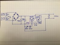
Need help to double check this schematic so no boo boos happen. It's rather complex and somewhat strange. It will be powering a turntable's motor. Thanks guys.
The unmarked capacitor is 4.7uF electrolytic.
The unmarked capacitor is 4.7uF electrolytic.
Attachments
Last edited:
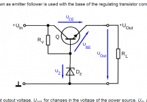
Wouldn't it be better to build a simple series pass regulator
with a zener diode as a voltage reference to a bjt? How many
amps does your motor need to get started ?
with a zener diode as a voltage reference to a bjt? How many
amps does your motor need to get started ?
It is a simple pass regulator. The driver emitter current is added to the output, which slightly adds to efficiency.
paul
paul
Wouldn't a shunt regulator have better performance noise wise?
An externally hosted image should be here but it was not working when we last tested it.
You'll struggle to get a clean and regulated 24 volt rail from an input of around 25 volts DC (18vac * 1.414) using a linear regulator.
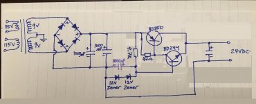
This looks more like an active ripple filter with zener limiter that stops the output going above 24 volts or should the input happen to be a bit higher.
This looks more like an active ripple filter with zener limiter that stops the output going above 24 volts or should the input happen to be a bit higher.
And if you draw it like this ? 😀Need help to double check this schematic so no boo boos happen. It's rather complex and somewhat strange. It will be powering a turntable's motor. Thanks guys.
The unmarked capacitor is 4.7uF electrolytic.
Just a compementary Darlington !
Mona
Attachments
Except the input voltage isn't high enough to get it to regulate well......
Just calculate the zener current and available base current to the NPN device. Ultimately though, I suspect non of this matters for its intended application as a motor PSU.
Just calculate the zener current and available base current to the NPN device. Ultimately though, I suspect non of this matters for its intended application as a motor PSU.
Since there is only polarity needed what about removing the center tap ground. That would give you 18VAC instead of 9VAC. Is the 24VDC output grounded?
Craig
Craig
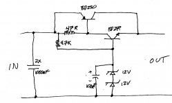
The transformer secondary should be wired for voltage doubling
and then drop 24 V on Zener and the rest (24V) on a resistor that
defines the Zener holding current with the load (motor) attached.
and then drop 24 V on Zener and the rest (24V) on a resistor that
defines the Zener holding current with the load (motor) attached.
- Status
- Not open for further replies.
- Home
- Amplifiers
- Solid State
- Turntable DC Supply 24V Very Complex/Strange