So I have been thinking exactly along these lines? The first stage is a differential circuit with an LPF filter. The second stage is a balanced to single ended converter which is unnecessary in my case because I need a balanced output. So I think in this schematic, either the left or the right channel (but not both) needs its analogue outputs inverted and whichever channel is inverted becomes the negative pin?
Is there somebody who can verify this?
If this works, it is very minimal modification to the DiyinHK board to get the mono output from the current L and R single ended outputs.
Appreciate your input n_dori
Sent from my iPad using Tapatalk
Actually the best differential circuit to use is probably the one recommended in AK4490 Datasheet. See Excerpt.
If this works, then there are no mods required to the DIYinHK board, simply connect to the L and R pins for the balanced mono output. That would be a big selling point for his board so I have asked him if he would be prepared to test this.
Attachments
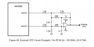
Ok so some further study has revealed a key difference between the AKM method and the Cirrus method. The op amp on the Cirrus diagram is configured as an adder/subtractor differential set up so the output will be proportional to the sum of the input voltages with the gain determined by the ratio of the resistors. Exactly what you want. The AKM op amp set up is a non inverting amplifier set up and the output is proportional to the average of the two input voltages.
So it looks like the Cirrus method works.
Sent from my iPhone using Tapatalk
So it looks like the Cirrus method works.
Sent from my iPhone using Tapatalk
Hi, both.Cubano, do you want balanced or unbalanced outputs or both?
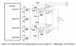
Well, there isn't any mono circuits shown in the ak4490 pdf but there is in the ak4497. If you compare figure 72 to figure 73 you can extrapolate a circuit from figure 41 of the ak4490 pdf and add the 2nd stage op amp to each output to get unbalanced outputs.
Attachments

You can get dual mono balanced outputs from the DiyinHK board without any modifications if you are using serial interface ( and you have to do so to get mono output from the AK4490).
In serial mode set register 02 mono and sellr bits. Additionally in register 05, set the bit for either Invr or invl bu not both.
You then get balanced mono output from the board from pin L and pin R. Whichever channel you inverted is the -ve terminal and the non inverted channel is the +ve pin.
You can't get both single ended and balanced outputs at the same time with this method.
Sent from my iPhone using Tapatalk
I have also used the circuit in Robs diagram but with different values of resistors and capacitors as I am using a current feedback op amp.
There is a DC offset on the output of around 7V on the output so you have to use DC blocking capacitors somewhere in the signal path with this method if your subsequent amp cannot tolerate this.
Sent from my iPhone using Tapatalk
There is a DC offset on the output of around 7V on the output so you have to use DC blocking capacitors somewhere in the signal path with this method if your subsequent amp cannot tolerate this.
Sent from my iPhone using Tapatalk
Thanks a lot for your answer. I will test it soon.
1- set mono channel and sellr on reg 2.
2- set INVL = 1 on reg 5
3- wire right =+ and wireleft = -
but i don't understand themystical for "Whichever channel you inverted is the -ve terminal and the non inverted channel is the +ve pin.
You can't get both single ended and balanced outputs at the same time with this method."
Sorry, i'm not a expert. Can you give me more detail, please?
I have never programmed the ak4490 before but I think you have to set the mono bit to 1 and the sellr bit to 0 for one of the dacs. This will send only left channel information to both the left and right outputs.
Then set the mono bit to 1 and the sellr bit to 1 on the other dac to send only right channel information to both left and right outputs. I hope that is right. Look at the ak4490pdf and this link.
https://hifiduino.wordpress.com/2014/12/07/akm-verita-4490-dac/
Then set the mono bit to 1 and the sellr bit to 1 on the other dac to send only right channel information to both left and right outputs. I hope that is right. Look at the ak4490pdf and this link.
https://hifiduino.wordpress.com/2014/12/07/akm-verita-4490-dac/
Here are the settings I would recommend.
Right channel board (My i2c address is 0x11 )
Register 02
Sellr=0
Mono=1
Register 5
InvL=1
InvR=0
Use pin R for +ve and pin L for -ve
Left channel board (my i2c address is 0x13)
Register 2
Sellr=1
Mono=1
Register 5
InvL=0
In R=1
Use pin L for +ve
Use pin R for -ve
With this method you are utilising both your left and right output pins on both your boards for the balanced output. To get single ended output from this you need to provide an external balanced to single ended stage. There are many examples of this stage in all the data sheets.
Sent from my iPhone using Tapatalk
Cubano, for the ak4497 circuit figure 73 the two outputs that are connect to the top op amp must be in phase as it shows. If they are out of phase they will cancel out to zero where they are join at the 44 ohm resistors. The two outputs connected to the bottom op amp must also be in phase.
However, the two outputs connected to the top op amp must be 180 degrees out of phase with the two outputs connected to the bottom op amp.
However, the two outputs connected to the top op amp must be 180 degrees out of phase with the two outputs connected to the bottom op amp.
thank you for your answer. I ended the connection and programming. I use the analog stage integrated in the card diyinhk with phase inversion.
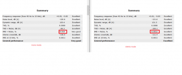
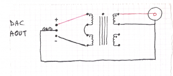
For the measurements, I need an unbalanced output. I use a transformer to unbalanced the signal. I measured the difference between mono and stereo with RMAA.
But the measures are bad in mono.
See the image. An idea?
For the measurements, I need an unbalanced output. I use a transformer to unbalanced the signal. I measured the difference between mono and stereo with RMAA.
But the measures are bad in mono.
See the image. An idea?
Attachments
thank you for your answer. I ended the connection and programming. I use the analog stage integrated in the card diyinhk with phase inversion.
For the measurements, I need an unbalanced output. I use a transformer to unbalanced the signal. I measured the difference between mono and stereo with RMAA.
But the measures are bad in mono.
See the image. An idea?
The stereo mode measures better in all respects?! Very strange!
One thing I forgot to mention is that I also synchronise the AK4490 chips on the two boards. Register 7 Synce bit on both left and right boards = 1.
Subjectively I heard an improvement over the stereo board but that could be because the driving current is doubled because of the two buffer stages in action?
Have you listened to the two set ups?
Can you please try and measure after synchronising the DAC chips? I would be very interested in the results.
Sent from my iPhone using Tapatalk
Sorry forgot to mention that the transformer is also probably responsible for the deterioration in results? Not sure how the professionals do it but probably use a balanced to single ended converter using a high quality op amp such as AD797?
Sent from my iPhone using Tapatalk
Sent from my iPhone using Tapatalk
Ok so this guy appears to be negative about RMAA at first glance but actually gives very good tips at the end of the article as to how to get good results from this.
http://nwavguy.blogspot.co.uk/2011/02/rightmark-audio-analyzer-rmaa.html?m=1
Sent from my iPhone using Tapatalk
http://nwavguy.blogspot.co.uk/2011/02/rightmark-audio-analyzer-rmaa.html?m=1
Sent from my iPhone using Tapatalk
RMAA is not precise. But it allows me to check my
test. I have no oscilloscope.
Cubano would it be possible to do the single ended test with the transformer in circuit. Just use the same connections on the transformer, the only difference being that the primary connection will be from L or R and Earth?
This should give you a true comparative result?
The best improvement you can expect from dual mono is theoretically 3dB. Personally I think it is easy to lose more than 3dB with a transformer in circuit.
Sent from my iPhone using Tapatalk
- Status
- This old topic is closed. If you want to reopen this topic, contact a moderator using the "Report Post" button.
- Home
- Source & Line
- Digital Line Level
- Dual Mono wiring for a Vout DAC