Greetings All!
New user, with a small project I would like to sort out myself.
About a year ago, I bought a second hand NAD 3220PE, which was said to be tested and working. This was simply to play some old vinyls through an inherited Ariston QDeck. It took me a while to sort everything out, and earlier on this year i finally hooked everything up to test it out. When i initially turned it on, after a few minutes it started to smoke, and only one channel worked properly. idiotically i didnt turn it off straight away and after a short time the music stopped and all that came through the speakers was semi-rhythmic clicking. After this i diconnected everything, and sent it to the local Hi-Fi shop to ascertain what was wrong with it. they reported it was uneconmical repair, and that both channels were completely destroyed [as written on the job sheet].
After this I decided to have a look myself, and as such took the lid off the unit to investigate. It seems that the main four transistors were mismatched, and there was evidence of two being replaced. I sourced a pair of both, noted their location and replace them - although I'm yet to solder them back on the board. The heat sink was cleaned, and the contact surfaces were cleaned and recovered in heat paste [the silver stuff I used for my PS3 repair a few years back] on inspecting the main board I found a number of other problems. A total of 4 resistors were fried. I've located the manual, and have a print out of the board layout and wiring diagram too. From interrogating this and the board itself I have found that the following resistors are fried:
R438 - 68 or 80 on the diagram, the text is distorted.
R440 - 220
R452 - 33
R453 - 180
I cant see the colour codes on any of them, and i have scoured the internet for some pictures of other peoples to try and see if i can get the colours of the burnt out resistors to replace them.
What I would like to ask is the following:
How do I work out the type of resistor from the numbers stated on the schematic?
What would be prudent to replace while I've got the entire thing apart? I'm happy to spend the money on parts to rebuild this and make it right again. if that means buying long list of parts and replacing them out to freshen up then I'm happy to do that.
Fact is, most of my experience is in cars, model aircraft building, RC cars, road bikes, architecture and drawing etc and aside from a few projects electronically orientated this will be a new venture for me. I've re-floated my PS3 mainboard six years ago while modifying the fan circuit so it hasnt overheated again. car wise I've re-soldered multi-relays, rewired a throttle actuator motor and retrofitted electric windows, electric seats and other thing in various old mercs in the past.
While I am probably starting from a basic level of understanding on how this amplifier works, I would like to work it out and fix it myself. I'm sure that there are better amplifiers to just buy, or it might be easier to just buy another, but I would like to fix this one. I picked an 80s NAD because my dad bought a 3130 in the 1980s and still has it, and its in perfect order save for a little crackle on the volume. It will be running a turntable, and perhaps a CD player or auxiliary output in the future.
So where do I start?
How do I work out the type of resistor from the numbers stated on the schematic?
What would be prudent to replace while I've got the entire thing apart?
Replacing the electrolytic capacitors is likely warranted.
Last edited:
Hi and welcome to DIYaudio. Yours seems a frequent problem for many UK newbies here, with many of your on-line sellers being obvious liars and you have been lumbered with the last guy's hopeless repair effort and a load of codswallop, or was that the line given by the previous owner to them?
Anyway, some comments: Don't try using silver loaded heat sink paste - that's for applying to plastic, insulated packages like ICs, CPUs in computers etc. The metal cases on the power transistors are +/- 28V, so the silver has a habit of shorting your power supply, no matter how careful you may be at applying it to the insulating mica washers/pads. Use new TO3 washers (hope you realise this all means the transistors need to be insulated from the heatsink) or use silicone elastomer types that don't need grease at all, if that seems difficult to do.
It is unlikely that's the only damage since replacement didn't work last time either. The driver transistors have likely blown too but you'll need to test for shorts, most likely C-E. The drivers are obsolete 2SD669/649 and whilst you can buy them and almost any unobtanium parts on Ebay, consider these will be copies, probably with a fake Hitachi logo and you can trust them about as far as much as the guy who sold you the amp. NOS parts are rare and expensive but check if you need them first. Genuine substitute parts would be a better option than correctly numbered fakes.
nad 3020e 3220pe integrated amplifier schematic Download page :: Schematics Unlimited
Cheers Ian, I'll refit the transistors with the correct stuff when I've got the new parts.
There wasn't any mention of a repair when I bought the amp, it was just sold as working, I don't remember seeing any evidence it had been opened before I took it to the repair shop. What makes me think it has been worked on was the mismatched transistors I could see through the vented case, and when I dismantled it further o found evidence of re soldering on their contacts.
The reason I want to fix this is that I'm unwilling g to roll the dice on buying another dodgy one, and I don't want to buy new. Also I like learning stuff.
Isis t know that about the paste, cheers for that.
Being a complete idiot, how do I test for shorts? I have a multimeter.
Ill work out which are the electrolytic capacitors and out that on the parts list.
How do I work out the blown resistors? I have a resistor colour decoder program but I don't know what the numbers on the schematics mean.
Most multimeters come with instructions for use and continuity testing (that is, measuring for a short or very low resistance) should be mentioned there. Often a beeper is also fitted as an audible continuity check for resistance below a specified threshold - often around 70 ohms. Collector to Emitter shorts are the most likely ones you will find and these will be a dead short ( virtually 0 ohms) and other components fitted won'r affect that measurement! You measur this with the power off and safely removed, then wait a few minutes until capacitors have discharged before measuring resistance on the lowest range or continuity.
You can often find manuals for specific digital multimeter models on the web, noting that some cheapo types are re-branded by many distributors and many that look alike, probably are. Otherwise, read a general guide to semi. testing with simple instruments, like this one: Testing semiconductors with analog and digital multimeters
Some cautions given in the article don't apply to simple audio transistors, the large 2N3055 type dating way back. If you need specific transistor details, Google is your friend - just type what you want to know in a few keywords (that's all search engines look for) and you can find mountains of info on any topic, particularly as your searches proceed and your field of interest is "learned" and becomes a resident part of your browser, as I'm sure you have found already.
Datasheets can be downloaded from archive sites. Most components you encounter will be obsolete and not all manufacturers will be known, such that you can refer to them, so it can become necessary to look at alternative manufacturers that could have supplied them too. Here's one archive I use which offers several manufacturers for comparison of details, marks etc: TRANSISTOR Datasheet catalog
Resistor colour codes are described in any number of charts, as you find. They don't come much simpler than this: Graphical Resistance Calculator
If you want to understand the multiplier symbols and conventional ways they are written on schematics, be warned, faceless bureaucrats will keep chopping and changing international conventions - so assume nothing remains the same for long. Here is a good general article on passive component values that you'll see numbered in shorthand form and lots of other coverage. Don't forget the power ratings for resistors - size is an indicator but all parts have shrunk and work hotter now than say, 25 years ago.
(see the article index - its a huge site) : Beginners' Guide to Electronics, Part 1 - Basic Components Explained
Thanks for that Ian, ill study those links etc in detail later on today.
In relation to the resistors, that's the first thing to work out, locate the obviously destroyed components and then look at testing all the others with a view to preventative my replacing others. This will require planning, research and organisation. This is going to be a good project, I'm going to learn a lot!
Ill post some pictures later on too of the problem areas.
ah!
right, so simple interrogation of the repair manual and the list of components allows me to ascertain the failed resistors and what they are.
thats that sorted.
There is a long list of capacitors. It seems easy enough to use the component list to buy new capacitors and transistors. obviously going into the data sheet for each transistor erm.. interesting.
is it worth going to some sort of specialist electrical shop that would be able to help with my massive list of parts?
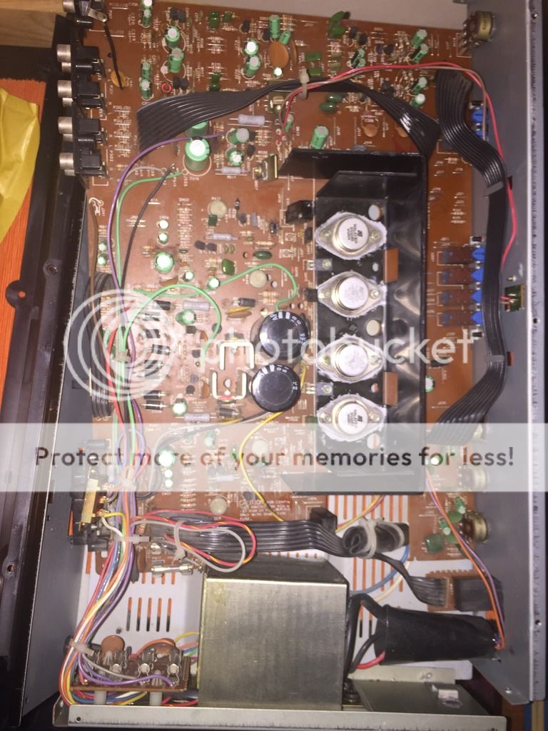
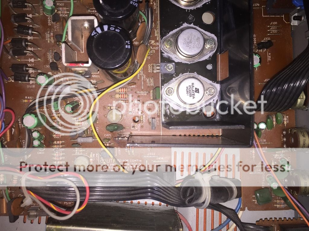
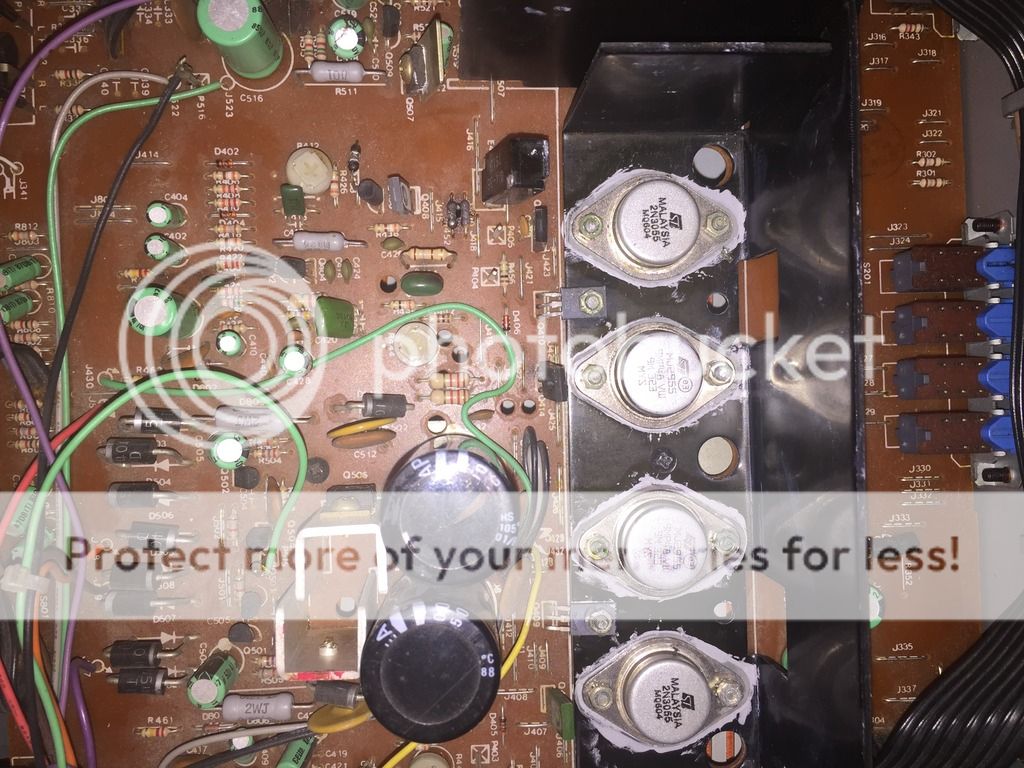
Pics of the amp, note the new transistors with the incorrect paste. ive got the new washers for those on my list.
right, so simple interrogation of the repair manual and the list of components allows me to ascertain the failed resistors and what they are.
thats that sorted.
There is a long list of capacitors. It seems easy enough to use the component list to buy new capacitors and transistors. obviously going into the data sheet for each transistor erm.. interesting.
is it worth going to some sort of specialist electrical shop that would be able to help with my massive list of parts?
Pics of the amp, note the new transistors with the incorrect paste. ive got the new washers for those on my list.
An externally hosted image should be here but it was not working when we last tested it.
An externally hosted image should be here but it was not working when we last tested it.
An externally hosted image should be here but it was not working when we last tested it.
Particularly as this is your first repair, don't try to replace everything imaginable at once.
The most likely outcome will be that the amplifier still won't work or smoke will appear before complete silence and leaves you with the thought that something you did was wrong somehow but you don't know where among the XX replacements you just did. Neither will anyone else! Powering up a dead amplifier that has only been repaired according to what looks stressed, often results in a repeat failure, taking out the replacements too and that becomes really frustrating.
Build a lightbulb limiter and fit it in the power line - talking full mains safety precautions and using approved 230V rated, sheathed cable and an insulated box to mount a standard ceiling mount light socket and outlet socket on, so containing any connections.
This means no open wires or connectors and that's not optional - safety is paramount. This will protect the amplifier from further damage by limiting current according to bulb power rating. A 40-60W bulb will be sufficient for a NAD3020/3220 etc. Obviously, the bulb glows with excess idle current but will flash brightly on start up anyway and then die back to a glimmer or nothing if the amplifier is not about to burn up again. Here's a schematic using UK parts, from the web - plenty of images there for examples.
First, only electrolytic caps will ever need replacing due to ageing and only a relative few will actually need it. Replace the 2 main smoothing electrolytics first and then tackle others grouped in their L & R channels, by turn, so that you always have a working channel for comparison by voltage measurements, with what you are currently doing.
Don't try to replace film capacitors (the greencaps) or resistors unless they are obviously damaged but do check diodes by measuring the forward voltage drop across them, per the article I linked to.
I suspect that one channel failed and the intrepid repairer realised by reading some forum that the output transitors would be blown, so replaced them all, hit the power switch and it worked sort-of for a period of time. Then he sold it quick. The power transistors are certainly recent replacements according to the newer ST micro brand markings on the 2N3055s. The MJ2955s could even be fakes so check whether the markings rub off with solvent.
I doubt the damage was all located and repaired and that's why it smoked on you - either that or your speakers or cables were shorted and the thermal fuses (E401 & 402) could not work fast enough - which is an inherent design weakness. Check driver transistors Q411-414 as described, for C-E shorts and B-E diode voltage. This will be a case of semiconductor failure and even though you replace the burnt resistors, if you don't locate the semis and any associated problems like shorts of the leads, excess solder shorting the PCB tracks etc, you'll be wasting your time and money.
The most likely outcome will be that the amplifier still won't work or smoke will appear before complete silence and leaves you with the thought that something you did was wrong somehow but you don't know where among the XX replacements you just did. Neither will anyone else! Powering up a dead amplifier that has only been repaired according to what looks stressed, often results in a repeat failure, taking out the replacements too and that becomes really frustrating.
Build a lightbulb limiter and fit it in the power line - talking full mains safety precautions and using approved 230V rated, sheathed cable and an insulated box to mount a standard ceiling mount light socket and outlet socket on, so containing any connections.
This means no open wires or connectors and that's not optional - safety is paramount. This will protect the amplifier from further damage by limiting current according to bulb power rating. A 40-60W bulb will be sufficient for a NAD3020/3220 etc. Obviously, the bulb glows with excess idle current but will flash brightly on start up anyway and then die back to a glimmer or nothing if the amplifier is not about to burn up again. Here's a schematic using UK parts, from the web - plenty of images there for examples.
An externally hosted image should be here but it was not working when we last tested it.
First, only electrolytic caps will ever need replacing due to ageing and only a relative few will actually need it. Replace the 2 main smoothing electrolytics first and then tackle others grouped in their L & R channels, by turn, so that you always have a working channel for comparison by voltage measurements, with what you are currently doing.
Don't try to replace film capacitors (the greencaps) or resistors unless they are obviously damaged but do check diodes by measuring the forward voltage drop across them, per the article I linked to.
I suspect that one channel failed and the intrepid repairer realised by reading some forum that the output transitors would be blown, so replaced them all, hit the power switch and it worked sort-of for a period of time. Then he sold it quick. The power transistors are certainly recent replacements according to the newer ST micro brand markings on the 2N3055s. The MJ2955s could even be fakes so check whether the markings rub off with solvent.
I doubt the damage was all located and repaired and that's why it smoked on you - either that or your speakers or cables were shorted and the thermal fuses (E401 & 402) could not work fast enough - which is an inherent design weakness. Check driver transistors Q411-414 as described, for C-E shorts and B-E diode voltage. This will be a case of semiconductor failure and even though you replace the burnt resistors, if you don't locate the semis and any associated problems like shorts of the leads, excess solder shorting the PCB tracks etc, you'll be wasting your time and money.
The transistors on the heat sink are what I've already done but they aren't soldered to the board yet. I'll get testing things with a multimeter 🙂 cheers for the in depth posts, I've got a lot to work out/do !
Speakers could have been dodgy, although they worked for a time.
I'll get testing and work out if everything is okay otherwise. If the speakers were to blame then would they have worked at all?
I'll get testing and work out if everything is okay otherwise. If the speakers were to blame then would they have worked at all?
When you replace the power transistors, 2N3055 / MJ2955 type only, set up the quiescent current or you may have a bonfire!
The procedure is explained within the service manual including where the links are to be desoldered.
The procedure is explained within the service manual including where the links are to be desoldered.
When you replace the power transistors, 2N3055 / MJ2955 type only, set up the quiescent current or you may have a bonfire!
The procedure is explained within the service manual including where the links are to be desoldered.
Thanks for that! ive just read the procedure on that. basically unsoldering a shorting jumper, adjusting some pots using multimeter and then when the desired figures are obtained resoldering the jumper.
im adding that to the list. the list is as follows for my works:
1. refit transistors without heat paste using silicon elastomer TO3 washers. check that they are fake.
2. test driver transistors for continuity - collector to emitter shorts
3. purchase and replace the 4 blown resistors
4. build lightbulb limiter with 40-60 watt bulb as per diagram and further research. I think ill be Ok to do that though
5. check all diodes by measuring forward voltage drop, as per previously linked article
6. check driver transistors Q411 to Q414 for C-E shorts and B-E diode voltage.
7. check excess solder shorts, leads, semiconductors.
8. recalibrate the quiescent current as per JonSnell's post.
after that, depending on what is uncovered etc I can reassemble it, and watch it catch fire, so I can throw it away and start again! haha. either that or it works and everything is fine. I'm fully aware that the plot will thicken as I delve deeper into this.
Heatsink thermal paste and all the stuff required for a perfect job is available through RS Components and you will find all you need there.
http://uk.rs-online.com/web/?cm_mmc=UK-PPC-0212-_-0RS_Brand_Terms-_-Top_Terms-_-rs
http://uk.rs-online.com/web/?cm_mmc=UK-PPC-0212-_-0RS_Brand_Terms-_-Top_Terms-_-rs
Heatsink thermal paste and all the stuff required for a perfect job is available through RS Components and you will find all you need there.
RS Components | Electronic and Electrical Components
cheers for that, i'll get my component list put into this. going to buy everything I could possibly need and then work through things bit by bit.
NAD 3020 3220PE Excellent Audiophile Upgrade + Repair + Restoration SERVICE | eBay
how much truth is in this ad in terms of the restoration work? I mean in terms of the upgrades - I'm not thinking of getting someone else to fix my amp.
how much truth is in this ad in terms of the restoration work? I mean in terms of the upgrades - I'm not thinking of getting someone else to fix my amp.
Last edited:
If you consider professional labour costs and the retail price of those high end blingware components, connectors, leads etc, I'd say it was a good deal for any high quality integrated power amp, provided the guy wasn't misleading you about what that quote didn't cover. If you also believe the extra shiny bits will improve your sound and extend the life of an old favourite amp, that's fine too.
Why anyone would try turd-polishing to that extent for a low budget consumer product, amazes me though. Were it a Mark Lev, Goldmund etc or an unusual design with cult status like Quad, I'm sure it's worth pro. work and appropriate quality parts but I think it makes much more sense to treat an entry level NAD as a DIY project that you don't lose too much cash on if you screw up.
As someone who has done restoration work more than once, I know there are more stories of screw-ups than most DIYs would call successful "upgrades" - it's just that you don't read the sad tales of guys with no clue what they were doing. I've learned to avoid any "upgraded" gear for that very reason.
Fair enough. I'm going to see if I can be in the minority of successful DIY repairers... As soon and I can find my bloody multimeter.
As has been mentioned a few times on this site; To upgrade, one must be more experienced than the design engineer who built it. To replace components with the original specification, is a refurbishment but to spend lots of money on "high end" components that are basically no better that what is already fitted, is foolhardy and at that point the fiddler convinces themselves that there has been "improvement".
As has been mentioned a few times on this site; To upgrade, one must be more experienced than the design engineer who built it. To replace components with the original specification, is a refurbishment but to spend lots of money on "high end" components that are basically no better that what is already fitted, is foolhardy and at that point the fiddler convinces themselves that there has been "improvement".
I agree. I thought it was a sales pitch amongst anything else
- Status
- Not open for further replies.
- Home
- Amplifiers
- Solid State
- NAD 3220PE Project