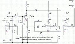
LTP= Long Tailed Pair, which can be done with valves as well as solid state.
Yes. Another word is Differential Stage.
Concertina is a nickname for a triode splitter that has equal resistors in anode and cathode.
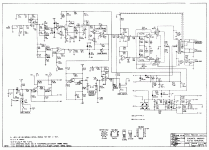
Here is a great design by Jean Hiraga based on a discrete solid state input stage (differential cascode) driving a pair of EL84's; it is called the "Pacific".
Published almost 30 years ago!
Amplificateur hybride Pacific (J.Hiraga)
Published almost 30 years ago!
Amplificateur hybride Pacific (J.Hiraga)
Last edited by a moderator:
Here is a great design by Jean Hiraga based on a discrete solid state input stage (differential cascode) driving a pair of EL84's; it is called the "Pacific".
Published almost 30 years ago!
Amplificateur hybride Pacific (J.Hiraga)
It is not a SS phase splitter, it just splits the same signal in-phase.
Hiraga corrected the mistake in the schematic in a later slightly different design.
The gate of the lower Jfet should be connected to ground through a 109 ohm resistor instead of connected to the input.
The gate of the lower Jfet should be connected to ground through a 109 ohm resistor instead of connected to the input.
Hiraga corrected the mistake in the schematic in a later slightly different design.
The gate of the lower Jfet should be connected to ground through a 109 ohm resistor instead of connected to the input.
Sure, this way it is as Dr. J. Curl prescribed. ;-)
But anyway it is a transistor LTP to replace a tube LTP.
I respect Hiraga, but it is not good to short inputs to the ground. ;-)
However, usually a balance pot is in the middle, so it is not a real problem. And ordinary linear pots for the gain can be used.
Also, it is a PITA to select 4 JFETs...
However, usually a balance pot is in the middle, so it is not a real problem. And ordinary linear pots for the gain can be used.
Also, it is a PITA to select 4 JFETs...
Last edited:
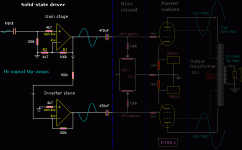
What I am looking for is a complete schematic like in the attached picture.
To make the gain stage (and phase splitter) with 2 opamps and next stage are KT88 in push pull. This will be a power amplifier as I already have a preamplifier (RCA outputs)
What could be a best op-amp to use in this schematic? To have enough gain
to drive KT88? I like very much its simplicity and that is why I am asking what was the final schematic that was tested in post number 32 from this topic. Even if in this case the final tubes were EL84 (if I remeber well).
Or, lets split this problem in 2. Does anyone made this first circuit part with opamps? If yes, please share the schematics and used components.
I would like to use tubes only in final output, and i would like to be KT88 ...
but I need this first part circuit.
Attachments
Any opamp has more than enough gain, but not all of them can swing high enough. What are you going to improve except number of tubes?
Any examples for opamps that can swing high enough to feed KT88?
Is more about the ideea of such a hybrid, its simplicity, but also: no hum, no noise, clear treble and bass, less chances for distorsing driving tubes or from external causes like RF , vibrations ... but in the end I would like to use those 4 KT88s 🙂
Can you recommend a simple schematic, KT88 push-pull, stereo power amp, full tubes, not expensive, no hum, no noise, ...? simple cathode biasing, UL or triode connection ...
The OPA604 (or 2604) can run on 48 volts as a total. Your diagram above needs protection for the opamp outputs as they are feeding onto a high voltage point (the grids).
A small series resistor and clamp diodes to the opamp rails would suffice.
A small series resistor and clamp diodes to the opamp rails would suffice.
Please be so kind and draw this complete circuit so I can see it ... 🙂 as for a newbe like me ...
(this OPA604 circuit for gain and phase split including protection)
(this OPA604 circuit for gain and phase split including protection)
OPA604 with +/- 24 volt rails cannot drive KT88 to full output.
The differential cascode input stages of these Hiraga amplifiers run on +/- 85 volt for a reason and can swing over 30 VRMS; that is what you would need to drive a KT88 output stage to begin with.
I doubt if you could find an IC to do the same job; to drive EL84 maybe yes, KT88 don't think so.
The differential cascode input stages of these Hiraga amplifiers run on +/- 85 volt for a reason and can swing over 30 VRMS; that is what you would need to drive a KT88 output stage to begin with.
I doubt if you could find an IC to do the same job; to drive EL84 maybe yes, KT88 don't think so.
TLC2057HV can run with up to +/- 60 volt rails.
Apex PA85 much more potent but would ruin your wallet.
Maybe worth looking into this (some additional circuitry to convert standard opamps into HV ones):
Make an Op-Amp High-Voltage Output Circuit - Electronics-Lab
Apex PA85 much more potent but would ruin your wallet.
Maybe worth looking into this (some additional circuitry to convert standard opamps into HV ones):
Make an Op-Amp High-Voltage Output Circuit - Electronics-Lab
OPA604 with +/- 24 volt rails cannot drive KT88 to full output.
The differential cascode input stages of these Hiraga amplifiers run on +/- 85 volt for a reason and can swing over 30 VRMS; that is what you would need to drive a KT88 output stage to begin with.
I doubt if you could find an IC to do the same job; to drive EL84 maybe yes, KT88 don't think so.
Fair point. That's shows my lack of familiarity with the practicalities of valve stages.
I've not investigated really high voltage standalone opamps (such as the LTC6090... but that is a CMOS input stage... hmmm) although adding discrete circuitry to an opamp as in Pieter's link is doable if a little component heavy.
- Status
- Not open for further replies.
- Home
- Amplifiers
- Tubes / Valves
- Has anyone used an opamp to split phase for a tube amp?


