What's the benefit of a balanced floating line driver, provided that it is connected to a balanced line receiver?
I've read some article from Bruno Putzeys, Bill Whitlock, Douglas Self etc., but failed to see any advantage in making the outputs floating (i.e. to mimic a transformer). I would think that a balanced receiver already takes care of eliminating common mode noise or whatsoever.
Am I missing something? Please, enlighten me.
Cheers, E.
PS: As a matter of fact, I only see disadvantages: increased complexity, noise, distortion or even instabilities.
Last edited:
Try this:
Balanced Line Driver with Floating Output
(Note: I don't get it myself yet - it'll probably make more sense to you than it does me, I just happened to have it in my bookmarks).
Balanced Line Driver with Floating Output
(Note: I don't get it myself yet - it'll probably make more sense to you than it does me, I just happened to have it in my bookmarks).
Hi Magic Matt,
I've that read that article too, but ik makes no sense to me at all.
It says: "A common voltage applied to the output will cause a considerable common mode current into the outputs - the output is not floating"
But nobody will apply a common voltage to the outputs. So what's "Elliott Sound Products" talking about anyway?
Do you see my problem with these highly sophisticated floating circuitry? It "sounds" just like overkill.
Cheers, E.
Wouldn't plugging into something like a computer with a low quality power supply result in that kind of thing? When I used to use my PC laptop plugged into the sound desk, I had to use a transformer between it and the desk because otherwise I got weird whistling noises etc. but since I've replaced the power supply for it that no longer happens. Perhaps it's related to preventing that?
One reason: With transformer outputs, you _must_ use both sides of the transformer or you have an open circuit. Hence, if using the transformer output single-ended, a person should ground one conductor of the balanced line. If someone does the same thing with an electronically balanced output that is not floating, that would be bad for two reasons: 1) you lose 6 dB of signal, and 2) There would be one op-amp with a shorted output, and having anything on the same circuit board going into current clipping would be a bad thing - could affect the power supplies or even generate a small amount of distortion audible on the ungrounded side.
The floating topology will allow one conductor to be grounded, and the other side will increase by 6dB to keep the differential output the same. I am never comfortable using just one conductor of a floating balanced output; if I need a single-ended signal I always ground the other conductor.
(This effect did make for some interesting situations in pro audio. If you have an electronically balance floating output, you _must_ ground one conductor to obtain a single-ended signal. If the electronically balanced output is not floating, you _must not_ ground one conductor to obtain a single-ended signal. I used to measure one conductor while I grounded the other - if the signal on the "+" conductor increased by 6 dB when I grounded the "-" conductor, I knew the output was a transformer or a floating output and that I should ground one conductor to obtain a single-ended signal.)
Another reason: If the electronically balanced output is not floating, each output has a rather low impedance path to ground (through the op-amp outputs). Hence, a difference in ground potentials between source and receiver could cause a common-mode current to flow in the signal wires. Theoretically, any voltage thus developed would be common mode and hence be rejected, but rejection is not always perfect and the signals resulting from ground differences can be large. On the other hand, if the receiving device has very high impedance inputs, such currents to ground should be quite small.
Tom
One reason: With transformer outputs, you _must_ use both sides of the transformer or you have an open circuit. Hence, if using the transformer output single-ended, a person should ground one conductor of the balanced line. ................
Yes I know, but I clearly wrote: " provided that it is connected to a balanced line receiver"
So please, skip this chapter about single-ended applications.
Yes, depending on the common mode impedance of the receiver. Does it matter? Not necessarily. It depends on the CMRR of the receiver.Another reason: If the electronically balanced output is not floating, each output has a rather low impedance path to ground (through the op-amp outputs). Hence, a difference in ground potentials between source and receiver could cause a common-mode current to flow in the signal wires.
Agreed. But the common mode rejection of a quasi floating line driver is at least as imperfect as the CMRR of the receiver. So little is gained by making the outputs floating. Right?Theoretically, any voltage thus developed would be common mode and hence be rejected, but rejection is not always perfect
How large? If it is really large, the electronics of the driver (and receiver) can't handle it anyway and clipping will results.and the signals resulting from ground differences can be large.
Exactly, and in most cases considerably higher than the output impedance of the driver.On the other hand, if the receiving device has very high impedance inputs, such currents to ground should be quite small.
Tom
So I still wonder what is gained with quasi (read: more or less) floating outputs.
BTW, in my first post I should have clearly stated that I meant quasi (thus electronically achieved) floating outputs, thus not by means of a transformer. Sorry guys for any confusion. 😱
Cheers, E.
Thanks, Edmond, I did not give enough consideration to your premiss that the receiver was balanced.
I wasn't really supporting any qualitative improvements in sound quality provided that the system is well-designed. I was thinking about why a manufacturer might want to have floating outputs - so that they will still perform well if someone grounds one side because they are accustomed to using transformer outputs. But that wasn't the question raised.
I think it is possible that a floating output is less susceptible to noise due to mismatched ground potentials than a non-floating one. But I agree that a good CMRR and good system design may make the difference imperceptible.
For issues of audio quality in a well-designed system, I can't think of a reason that the floating output should have better sound quality.
Tom
Thanks Tom for reply and I'm glad we don't disagree about this subject.
BTW, one of the reasons I started this thread was that the balanced outputs my L22 sound cards are rather ill designed. So I thought: f*** off with this floating nonsense, it makes things only worse (see: this post)
Cheers, E.
BTW, one of the reasons I started this thread was that the balanced outputs my L22 sound cards are rather ill designed. So I thought: f*** off with this floating nonsense, it makes things only worse (see: this post)
Cheers, E.
Last edited:
Computer sound cards? Trust me, if somebody can hook those up wrong, they will. They're probably anticipating that somebody will put an unbalanced lead into a balanced output, or unbalanced input on something. When dealing with computer audio, you can pretty much guarantee it, regardless of how expensive the card, because some people think spending money is a substitute for knowledge. As a computer tech. I can probably give you a few crazy examples too!
What's the benefit of a balanced floating line driver, provided that it is connected to a balanced line receiver?
I've read some article from Bruno Putzeys, Bill Whitlock, Douglas Self etc., but failed to see any advantage in making the outputs floating (i.e. to mimic a transformer). I would think that a balanced receiver already takes care of eliminating common mode noise or whatsoever.
Am I missing something? Please, enlighten me.
Traditional balanced signaling offers noise immunity for interconnections, but it also offers the possibility of eliminating signal current traveling within ground between devices, or within a device. Adding the refinement of a high common mode driving impedance further reduces signal current traveling within ground, compared to a system without high output common mode impedance. Why is that good? It allows a large system to be connected without any surprises, such as crosstalk or colorations caused by these less than ideal signal currents, altered by the decidedly non-flat CMRR curves, traveling where they should not, and causing a possibly audible coloration.
While "the balanced receiver already takes care of that" is an easy thing to say, the CMRR of most receivers is actually pretty poor at audio frequencies. CMRR usually quoted at 60Hz with impressively high numbers, but even at 1kHz, CMRR pretty poor with most practical circuits. Even if one uses pricey, close tolerance resistors, it's hard to get more than 50-60dB of CMRR at 1kHz with a typical active balanced receiver circuit. This is not an enormous number, so it's still worth optimizing the system as a whole, which includes the driving circuit, not just the receiver.
When driven with a high common mode output impedance, a real world active balanced receiver, even one made with expensive components, is going to perform a lot better, despite the realities of imperfect resistors, time, and temperature.
To summarize, the reason is both that it makes the receiver circuit work better, and it also greatly reduces signal currents traveling within ground. The second point is one that most folks typically ignore - "balanced" usually means nothing more than "noise immunity", but there are other reasons why a balanced connection can be superior. In a simple system with two devices, it may not be so important, but in a typical production studio with hundreds of signals routed among the devices, it can add up to a problem worthy of attention.
Hi Monte McGuire,[..]
While "the balanced receiver already takes care of that" is an easy thing to say, the CMRR of most receivers is actually pretty poor at audio frequencies. CMRR usually quoted at 60Hz with impressively high numbers, but even at 1kHz, CMRR pretty poor with most practical circuits. Even if one uses pricey, close tolerance resistors, it's hard to get more than 50-60dB of CMRR at 1kHz with a typical active balanced receiver circuit. This is not an enormous number, so it's still worth optimizing the system as a whole, which includes the driving circuit, not just the receiver.
[..]
So you're saying that because the CMRR of a line receiver is (generally) rather poor, it helps to drive it with floating outputs, right?
Now, let's have a look at the line drivers and receivers from THAT: The CMRR of the 1200 series receivers are 85...90dB, while the CMRR of the 1646 driver is 65dB. That's 20...25dB less compared to the receivers. As far as I can see, this contributes almost nothing to the overall CMRR.
As for the Lynx L22, I don't have CMRR figures, but I do have CM impedances.
For the receiver: 6kOhms and driver: 1.8kOhms (at 1kHz). Again, the latter is considerably lower than the former (besides, I wouldn't call an impedance of only 1.8k "floating"). And again, this will contribute almost nothing to the overall CMRR.
This is why I have little confidence in quasi floating outputs.
Maybe you know of examples that put floating outputs in a better light than above figures. Please, let me know.
>When driven with a high common mode output impedance, a real world active balanced receiver, even one made with expensive components, is going to perform a lot better, despite the realities of imperfect resistors, time, and temperature.
How much better?
Cheers, E.
Last edited:
I believe you immediatly, but I'm eager to learn about "crazy examples".[...]
As a computer tech. I can probably give you a few crazy examples too!
Cheers, E.
[..]
When driven with a high common mode output impedance, a real world active balanced receiver, even one made with expensive components, is going to perform a lot better, despite the realities of imperfect resistors, time, and temperature.
To summarize, the reason is both that it makes the receiver circuit work better, and it also greatly reduces signal currents traveling within ground.
[..]
Hi Monte McGuire,
I did a few simulation with the line driver of the Lynx L22, which has a CMRR of 29dB and a "synthetic" line receiver with CMRR of 40dB and an input impedance of 12k (wrt gnd).
With the floating stuff on the ouputs disabled, the overall CMRR is (of course) 40dB, while floating stuff enabled, I got 42.3dB. That's an improvement of 2.3dB. Not a big deal, I would say.
Regarding signal currents, they dropped by 19%. Again, not a big deal.
Cheers, E.
NB: By "synthetic" I mean built around analog primitives.
Solid state non XFMR driver/rcvrs are bridged network systems, which determine CMR
It helps in understanding to look at the driver / rcvr system as a bridge, which of course it is. High CMR results when drivers have low Zout and rcvrs high Zin.
Robert Demrow wrote a classic article on this topic many years ago. See Refs in this article.
It helps in understanding to look at the driver / rcvr system as a bridge, which of course it is. High CMR results when drivers have low Zout and rcvrs high Zin.
Robert Demrow wrote a classic article on this topic many years ago. See Refs in this article.
Hi Monte McGuire,
I did a few simulation with the line driver of the Lynx L22, which has a CMRR of 29dB and a "synthetic" line receiver with CMRR of 40dB and an input impedance of 12k (wrt gnd).
With the floating stuff on the ouputs disabled, the overall CMRR is (of course) 40dB, while floating stuff enabled, I got 42.3dB. That's an improvement of 2.3dB. Not a big deal, I would say.
Regarding signal currents, they dropped by 19%. Again, not a big deal.
Cheers, E.
NB: By "synthetic" I mean built around analog primitives.
Hi Edmond,
How did you achieve these Lynx22 figures that you mention.
I use this board for many years much to my satisfaction.
A CMRR of the output of 29dB is not documented anywhere, and I have no clue what in this case an output CMRR means.
And a CMRR of 40dB for an input is also a bit hard to understand, since CMRR has to be measured with the transmitter and receiver in combination. But may be you mean something different.
Anyhow, I do not understand your question.
Hans
It helps in understanding to look at the driver / rcvr system as a bridge, which of course it is. High CMR results when drivers have low Zout and rcvrs high Zin.
Robert Demrow wrote a classic article on this topic many years ago. See Refs in this article.
Hi Walt,
Thanks for the refs. These articles pretty much confirm my own thoughts about common mode issues. You also mentioned using a transformer to reduce CMR even further. However, the center tap (of the transformer) was grounded, so far so good. But I have questions about line drivers with quasi floating outputs. (also referred to as "electronically balanced"). That's what this thread is about. I hope you can also shed some light on this specific topic.
Cheers, E.
Hi Hans,
Cheers, E.
I've reverse engineered (part of) the L22 and subsequently simulated the circuit.Hi Edmond,
How did you achieve these Lynx22 figures that you mention.
Sure, it is one of best cards you can get (thought it is not perfect in every respect).I use this board for many years much to my satisfaction.
That's right. This figure is obtained by means of simulating the line driver.A CMRR of the output of 29dB is not documented anywhere,
See picture below.and I have no clue what in this case an output CMRR means.
Every balanced line receiver has a CMRR, also in isolation. So I don't understand why you don't understand it.And a CMRR of 40dB for an input is also a bit hard to understand, since CMRR has to be measured with the transmitter and receiver in combination. But may be you mean something different.
Anyhow, I do not understand your question.
Hans
Cheers, E.
Attachments
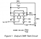
-29dB output CMRR as you define it, roughly means that the output impedance of one leg is 10 Ohm higher, at least at the frequency that you used for your measurement.Hi Hans,
That's right. This figure is obtained by means of simulating the line driver.
See picture below.
Cheers, E.
That is interesting information, but only for a receiver that has a low input impedance. With 10K input resistance you could still get -60dB CMRR.
I will read the Thread from the beginning, and try to better understand what you are looking for.
Hans
After having read the postings I see your point.
My feeling is that floating was invented to simulate a transformer, to give a sort of comfortable feeling to those used to working with transformers.
However a transformer can easily bridge a large voltage difference between sender and receiver, whereas a floating balanced output is limited by its supply voltage, so it is a crippled version of a trafo.
Your question is if a floating balanced output has any benefit when used with a balanced input.
In principle I see no benefit at all, be it that the CMRR of a receiver may be dependent to some degree on the average level of the incoming signal.
CMRR of a receiver is mostly specified with signals having their average value at zero volt.
Keeping the Rms value of the signal the same, but lifting the average value from zero to 10 Volt, will in many cases result in a lesser CMRR.
A floating output in that case will try to diminish the average value, and therefore give a slightly better CMRR.
This situation might occur when sender and receiver are far apart and connected to a mains with a different earth potential.
In those cases a transformer is a better solution to start with.
So to my opinion, having a floating output for "normal" use is only of academic advantage, but has many potential disadvantages as you have mentioned like: increased complexity, noise, distortion and instabilities.
Hans
- Status
- Not open for further replies.
- Home
- Source & Line
- Analog Line Level
- What's the benefit of a balanced floating line driver anyhow?