Hi guys!
I camed up with an idea, you can see down here:
![DSC_0263[1].jpg](https://www.diyaudio.com/community/data/attachments/508/508555-ed110d750f7ea954c1982b8fc7b0b403.jpg?hash=7RENdQ9-qV "DSC_0263[1].jpg")
It's a long tailed pair driving qasicomplementary push pull configuration. Bias is not optimised yet, it's only about topology. What do you think?
Best regards
Mike
I camed up with an idea, you can see down here:
It's a long tailed pair driving qasicomplementary push pull configuration. Bias is not optimised yet, it's only about topology. What do you think?
Best regards
Mike
It will work , but you have to " balance " the impedance of the lower half ( of 6922 ) with the upper half ! .
The only way to tell if it will be an improvement over simpler design is to simulate it - everything else is just guesswork.
Shoog
Shoog
It appears to be much like Broskie's unbalancer circuit, except with feedback applied.
Balanced to unbalanced
Balanced to unbalanced
Balance impedance between upper and lower tube? I don't understand, what unbalance you are talking about... If you could explain, that would be great 🙂 Still a newb.
The upper triode have lower output impedance than the lower tride , there are too many methodes to balance them , search for otl headphone amplifiers theory to understand what I mean , or take a look here ... V-to-I Amplifers .Balance impedance between upper and lower tube? I don't understand, what unbalance you are talking about... If you could explain, that would be great 🙂 Still a newb.
Not only the output impedance , the gain of the lower triode have to be compensated too ! , because it is a grounded cathode circuit and the upper triode is a cathode follower ! .
Last edited:
Rephrashing what Dimitris said: The problem with the output stage topology is that the upper triode's cathode is moving along with the output signal while the bottom triode's cathode is fixed to ground. So, the upper triode needs to be driven with more swing than the lower one.
Hi,
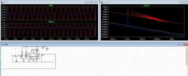
Did a simulation of your circuit idea, just for fun. Look at the attachment.
Tells a lot about the circuit performance, as it is on your drawing.
Did a simulation of your circuit idea, just for fun. Look at the attachment.
Tells a lot about the circuit performance, as it is on your drawing.
Attachments
Last edited:
Hi,
Did a simulation of your circuit idea, just for fun. Look at the attachment.
Tells a lot about the circuit performance, as it is on your drawing.
Thanks! I guess the distortion of signal is due to the gain difference between the halves, right?
I see that Broskie used local feedback to set gain of both halves to half, maybe this is a way to go...?
Hi,
Did a simulation of your circuit idea, just for fun. Look at the attachment.
Tells a lot about the circuit performance, as it is on your drawing.
Which was my point, a simulation short cuts a thousand guesses.
It seems that the circuit is a long way from been optimised - but more probably that a simpler circuit will do better.
Shoog
Which was my point, a simulation short cuts a thousand guesses.
It seems that the circuit is a long way from been optimised - but more probably that a simpler circuit will do better.
Shoog
Could not agree more..
Simulation is good and it is the easy way and many times is used by people who don't have a lot of experience to " read " right a circuit and tell if it work well or not ! .
I read all the mateirals you brought, thank you. Now I feel stupid, for not digging enough. My goal is to make a preamp (obviously very good, etc...) that has high driving abilities, as I use low input impedance amplifier (like 20k) and I'm sometimes testing some stuff. Will the unbalancer output stage work connected to my gain stage with some feedback attached? No need to blow up the open door I guess. Or some sort of actively loaded cathode follower, like Aikido Cathode Follower. Which way you feel better about?
It doesn't need to be actively loaded, but you can if you want. 20k is not that hard to drive. For example, a simple ECC88 cathode follower with a resistor load will drive 10Vrms into 22k with less than 0.1% THD.My goal is to make a preamp that has high driving abilities, as I use low input impedance amplifier (like 20k)... Or some sort of actively loaded cathode follower, like Aikido Cathode Follower. Which way you feel better about?
A White cathode follower or CCS-loaded cathode follower would do even better.
I think you are reinventing the wheel when Aikido and SLCF do exactly what you want out of the box.I read all the mateirals you brought, thank you. Now I feel stupid, for not digging enough. My goal is to make a preamp (obviously very good, etc...) that has high driving abilities, as I use low input impedance amplifier (like 20k) and I'm sometimes testing some stuff. Will the unbalancer output stage work connected to my gain stage with some feedback attached? No need to blow up the open door I guess. Or some sort of actively loaded cathode follower, like Aikido Cathode Follower. Which way you feel better about?
As a learning experience the use of Spice simulations is extremely valuable, if you had have simulated your design you could have discovered its issues and then made adjustments to improve them. By close observation you could learn exactly what function each component plays in the design and if you are systematic about it I fairly much guarantee that you will have more knowledge of valve design at the end of the process.
Shoog
Last edited:
"""""""" I read all the mateirals you brought, thank you. Now I feel stupid, for not digging enough. My goal is to make a preamp (obviously very good, etc...) that has high driving abilities, as I use low input impedance amplifier (like 20k) and I'm sometimes testing some stuff. Will the unbalancer output stage work connected to my gain stage with some feedback attached? No need to blow up the open door I guess. Or some sort of actively loaded cathode follower, like Aikido Cathode Follower. Which way you feel better about? """"""""
I think it is better for you ( as a newb ) to use a cathode follower ( or an actively loaded cathode follower ) for the output stage , but if you want to keep your output stage , which is a SEPP ( Single Ended Push Pull stage ) you will have to add one more stage to balance the differences in gain and impedance ! . But then the circuit will became more complex , for example see this scheme ...
I think it is better for you ( as a newb ) to use a cathode follower ( or an actively loaded cathode follower ) for the output stage , but if you want to keep your output stage , which is a SEPP ( Single Ended Push Pull stage ) you will have to add one more stage to balance the differences in gain and impedance ! . But then the circuit will became more complex , for example see this scheme ...
Attachments
Last edited:
I think I'll go for LTP with BJT current sink, and cathode follower with resistor load (maybe change it for active later). Global feedback. Right now I'm struggling with getting tube models into spice.
Last edited:
- Status
- Not open for further replies.
- Home
- Amplifiers
- Tubes / Valves
- Unusual tube preamp, will it work?