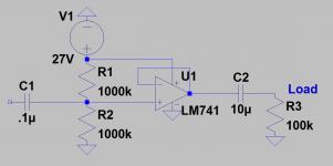
Hi, for whatever reason, I do not have good results with op amps, I'm sure its me . I have a guitar I'm running into an amp module that is 100k input impedance and I want 1meg input impedance. So I tried to make this buffer. I have 741 op amps and made the circuit which is attached. Sometimes I hear a weak sound other times I don't. I added a 6.8uf capacitor across R2 and that didn't help. Then I tried replacing with a tl081 with and without capacitor. Then I used a 9v batter with the tl081. In the past I've tried to hook up op amps I get them to work about 25% the time. Are they really that finicky? I may try a jfet buffer, seems to me I never have problems with transistor circuits.
As an aside question, is there a very stable unipolar powered audio op amp that is hard to get wrong? Preferably 9volt.
As an aside question, is there a very stable unipolar powered audio op amp that is hard to get wrong? Preferably 9volt.
Attachments
Rather than spoonfeed an answer, it would be better to understand how opamps - in fact any amps work and their circuit arrangement requirements to do it effectively. Have a serious read here, with attention to the high impedance amplifier section.
Audio Designs With Opamps
Audio Designs With Opamps
I have a guitar I'm running into an amp module that is 100k input impedance and I want 1meg input impedance. Sometimes I hear a weak sound other times I don't. I added a 6.8uf capacitor across R2 and that didn't help. Then I tried replacing with a tl081 with and without capacitor. Then I used a 9v batter with the tl081. Are they really that finicky? I may try a jfet buffer, seems to me I never have problems with transistor circuits.
Your circuit is basically fine, but you may heve *built* it wrong.
Ok, we all have to start from 0 😛
1) you are not mentioning pin numbers, and I *suspect* you are counting them the wrong way or something.
Are you protoboarding this?
If not, go buy one first thing in the morning.
2) when properly wired, you will have 0V (ground) on pin 4 ; +V (9 or 27V) on pin 7 ; half +V on pin 6 and a little less on pin 3 because your meter will pull that voltage down somewhat while measuring.
Unwritten rule: first try to have proper DC at different points, only then start worrying about AC (audio).
3) now check wiring to ensure that guitar audio gets to circuit input, that output goes to your amp, etc.
Download Op Amp datasheet and triple check pinout.
4) do NOT place a capacitor in parallel across R2: it will short all audio to ground.
5) now to minor matters: as is your input impedance will be somewhat less than 400k , because both 1M resistors are in parallel as far as audio is concerned, and 741 does not have a great input impedance either; for true 1M impedance use 2M2 biasing resistors and a FET input Op Amp (TL071/081/LF353/etc.) but tht's not the main point, your circuit should work as is.
6) in general, start by protoboarding simple circuits first, and study along that, theory and practice go hand in hand and help each other.
And congratulations on starting this hobby

Well I just pulled that off the amz basic buffers webpagehttp://www.muzique.com/lab/buffers.htm
Thank you Ian for the link. I read but I will have to reread several times because it takes a while for me to get this.
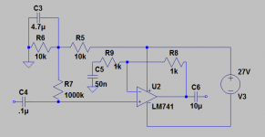
If I had to make up my own buffer I guess from what I read I would do this: a noninverting amp with gain of 1 and uses the impedance of the op amp + input which is very high at least 1 Meg. See attached. Am I on the right track here?
Thank you Ian for the link. I read but I will have to reread several times because it takes a while for me to get this.
If I had to make up my own buffer I guess from what I read I would do this: a noninverting amp with gain of 1 and uses the impedance of the op amp + input which is very high at least 1 Meg. See attached. Am I on the right track here?
Attachments
What is it about your guitar that requires this change? A piezo pickup maybe? What symptom occurs when you plug straight into the amp and you want to cure?
Thank you JMFahey for the great reply. I will simply try to rebuild tomorrow with particular attention to the pins. And that is great advice to check the voltages of the pins. Makes perfect sense. I'm sure I'll get this soon. Thanks again!
I will simply try to rebuild tomorrow with particular attention to the pins.
Remember that the op amp's pins are counted clockwise, as seen from the bottom.
The dot on the top of the IC package is next to pin #1.
Why? This is a carry-over from tube sockets before pcbs, which you can only wire from the bottom.
Hence, it was natural to count clockwise as seen from that side (starting at the socket's space or notch).
This is still the case even for smt (surface mount) packages, where there IS no bottom!
Last edited:
Looking down on the top of the 8pin DIL package the pins are numbered counter-clockwise.
Notch or dot to the left.
Lower/bottom row of 4 pins running left to right.
Left most is pin1 and rightmost is pin4.
Above pin4 is pin5 . Counting right to left along the top row, you have 5 to 8. pin8 is above pin1.
Looking at the top side of the PCB, the pads are also counted from lower left at the notch as pad1 and go counterclockwise to end up at topleft with pad8.
Last edited:
not sure where this wire/connection goes on my op amp circuit
Hi all,
I'm trying to figure out how I'm supposed to hook up this op amp. I believe I have biased the op amp correctly with this single supply. I have a noninverting configuration, but conceptually I'm not sure if this should go to the bias voltage (1 left the wire hanging between the two choices), or if I should use a capacitor to pass the ac voltage to the actual ground. Or, am I supposed to do something else. What do people usually do. I'm having trouble getting my brain around this for some reason.
This is an amp with about a gain of 3 that I need for a preamp section I am building. It has to have an input impedance of about 1meg and an output impedance of under 1k.
Attachments
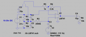
It looks electrically OK to me. R5 should connect to C5. AC coupling the feedback like that returns the gain of the opamp to unity at DC (a good thing generally 🙂)
Now 2meg as an input resistor is getting a bit on the high side for an opamp like the 741, particularly with the low values used for R4 and R5. Without going to deep into the reasons why, this imbalance could cause the output to take on a DC voltage higher or lower than the expected 'half supply' voltage.
A FET device like the TL081 would be immune to that. Try the 741 though. If the DC output voltage on pin 6 is significantly different to Vsupply/2 then you need to look at using a different opamp with much lower input bias currents (such as FET).
Try increasing the ratio of C2:C1 try 100uF:0.1uF, maybe remove C1.
Then change R3 to 220k & change C3 to 470nF.
And finally remove the link from C5 to C2.
Then change R3 to 220k & change C3 to 470nF.
And finally remove the link from C5 to C2.
newbie simple op amp design powering from a transformer
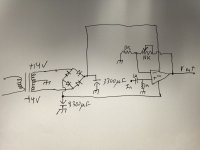
Ok I have been studying this a little. Unfortunately I've been on the road, so I haven't tested anything, but I will. So here is a basic op amp application. gain 2-11 noninverting amplifier. I wanted to get basic feedback on this schematic to make sure there are no major issues. I was going to build it with the 741 as a right of passage, but I have tl071, tl081 i can put in the IC socket to try out also.
Ok I have been studying this a little. Unfortunately I've been on the road, so I haven't tested anything, but I will. So here is a basic op amp application. gain 2-11 noninverting amplifier. I wanted to get basic feedback on this schematic to make sure there are no major issues. I was going to build it with the 741 as a right of passage, but I have tl071, tl081 i can put in the IC socket to try out also.
Attachments
I wanted to get basic feedback on this schematic to make sure there are no major issues.
If those are +/-14VAC secondary voltages, the power supply voltages will be a little high,
around +/-20V. Use 3 terminal regulators to reduce them to +/-15V each.
Last edited:
As above, plus you will find a massive difference between the TLO71/81 FET opamp and the 741 in the form of the DC voltage that will appear at the amplifier output. The 741 will generate 'offset' errors due to the small but finite DC currents that flow from the opamp input pins. These currents generate tiny voltages that get amplified by the gain of the circuit. The FET type does not suffer this.
Thank you
Ok thank you for the critique. I am going to put a 22uf capacitor at the output so I don't injure the amp I will plug it into. And I actually listed the transformer wrong, it is 14volt amplitude, 28 volts peak to peak so I think I'll be ok there.
Ok thank you for the critique. I am going to put a 22uf capacitor at the output so I don't injure the amp I will plug it into. And I actually listed the transformer wrong, it is 14volt amplitude, 28 volts peak to peak so I think I'll be ok there.
Put 0.1uF bypass caps as close as possible to power supply pins of opamp. 741's are rather general purpose old tech. You might want to get audio grade JFET input ones as suggested by others.
If you have some time and 6 to 9 spare transistors you may find making your own high performance audio opamp a worthwhile endeavor.
https://www.passdiy.com/pdf/diyopamp.pdf
https://www.passdiy.com/pdf/diyopamp.pdf
- Status
- Not open for further replies.
- Home
- Amplifiers
- Solid State
- Please help, can't seem to get Op Amp to work right