Hi all,
I have a few questions about this circuit. I'll ask the questions first, then describe the circuit a little.
Questions are: "What is the input impedance of this circuit, and why doesn't it sound worse."
There is no emitter resistor, and as far as know that should drastically decrease the input impedance of the circuit. I was thinking there should be about a 1k emitter resistor to maintain input impedance for a guitar. I thought I would put a 20k pot in series with 680ohms to make a drive control. As an experiment I just put the 20k pot allowing for the emitter resistance to go to zero. It seemed to work fine.
I'm guessing there's a very low input impedance, but an arbitrarily high gain 100k/0ohms and the gain is winning, but either way I'd like to sort of know what to use as the input impedance for the circuit is. I'm not even sure how to measure it because the waveform is so distorted.
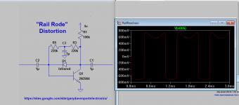
This was my experiment to see how simple of a distortion circuit I could make with one 2n3904 transistor. The 100k collector resistor makes the bottom of the sine wave get clipped around .7v. The infrared led is in the feedback loop and clips the top at about .7v. Usually like in electra distortions, there is a 470k resistor, but I split this into two 220k resistors and put a .1uf capacitor to ground to increase gain (I'm actually not sure how that works but I saw it in Joe Davisson's Easy Drive Circuit and tried it as a mod. Analog Alchemy)
I think the output impedance should be about 100k so that lets me feed it into a 1meg input guitar amp.
Anyhow, for as simple as it is I don't think it sounds too bad. I ran it through a marshall type tonestack and it seemed to be acceptable to me for a simple build.
Thanks for looking and any help on figuring out the input impedance or other insights would be appreciated.
I have a few questions about this circuit. I'll ask the questions first, then describe the circuit a little.
Questions are: "What is the input impedance of this circuit, and why doesn't it sound worse."
There is no emitter resistor, and as far as know that should drastically decrease the input impedance of the circuit. I was thinking there should be about a 1k emitter resistor to maintain input impedance for a guitar. I thought I would put a 20k pot in series with 680ohms to make a drive control. As an experiment I just put the 20k pot allowing for the emitter resistance to go to zero. It seemed to work fine.
I'm guessing there's a very low input impedance, but an arbitrarily high gain 100k/0ohms and the gain is winning, but either way I'd like to sort of know what to use as the input impedance for the circuit is. I'm not even sure how to measure it because the waveform is so distorted.
This was my experiment to see how simple of a distortion circuit I could make with one 2n3904 transistor. The 100k collector resistor makes the bottom of the sine wave get clipped around .7v. The infrared led is in the feedback loop and clips the top at about .7v. Usually like in electra distortions, there is a 470k resistor, but I split this into two 220k resistors and put a .1uf capacitor to ground to increase gain (I'm actually not sure how that works but I saw it in Joe Davisson's Easy Drive Circuit and tried it as a mod. Analog Alchemy)
I think the output impedance should be about 100k so that lets me feed it into a 1meg input guitar amp.
Anyhow, for as simple as it is I don't think it sounds too bad. I ran it through a marshall type tonestack and it seemed to be acceptable to me for a simple build.
Thanks for looking and any help on figuring out the input impedance or other insights would be appreciated.
Attachments
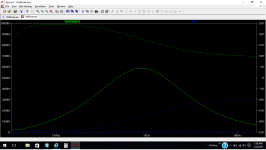
Put an AC voltage source at the input, do an AC simulation, plot V(input node)/I(Voltage source) and make the vertical scale linear. You'll get a graph of input impedance vs. freq.
Cheers,
Cabirio
Cheers,
Cabirio
Ok Cabirio I will try that next.
I just put a series resistor of 100000k signal path and measured the voltage drop and it dropped from .160mv to .00088mv. I had to put such a large resistor in series to get the signal to not clip at the measurement point. Not sure if that is valid, but it gave me an input impedance of 550k using the Measuring input impedance and calculating output impedance calculation calculate audio amplifier op-amp how to measure impedance voltage gain total loudspeaker speaker microphone resistance resistor bridging matching test load loudspeaker source resi sengpielaudio calculator.
I just put a series resistor of 100000k signal path and measured the voltage drop and it dropped from .160mv to .00088mv. I had to put such a large resistor in series to get the signal to not clip at the measurement point. Not sure if that is valid, but it gave me an input impedance of 550k using the Measuring input impedance and calculating output impedance calculation calculate audio amplifier op-amp how to measure impedance voltage gain total loudspeaker speaker microphone resistance resistor bridging matching test load loudspeaker source resi sengpielaudio calculator.
The 2n3904 has one of the most comprehensive datasheets available. Have a look at the bottom of page 5. https://www.google.com/url?sa=t&rct...NVJQRLK_w&sig2=gIeP0LE4R95R2l99iTXxVg&cad=rja
Input impedance is around 30000/40000 ohms.
And you *do* have an emitter resistor, around 430 ohms to be precise.
To boot, gain is not 100k/0 but 100k/430 ... that without NFB and infinite resistance load, so in the Real World I would expect around 50X .
I estimate Hfe around 100 which to me is a reasonable value for an average general purpose transistor.
Try to understand how things work, in this case a single stage bipolar gain stage; simulators can be powerful tools ... and also a rock tied to your neck if all you do is mindlessly throw numbers at it, get numbers in return ... and don't exactly understand what they show or mean.
I wouldn't even try to calculate it 😀
If you want to know, just measure it.
The output impedance is irrelevant, it's lower than the input impedance it's feeding (by more than it needs to be) - it will also be considerably less than 100k (again I'd measure it if I wanted to know).
As for why it '"doesn't sound worse", it's a distortion unit, it's supposed to sound absolutely crap - so it couldn't really "sound worse" 😛
Here is the impedance plot
Thanks everyone. Took me a little while to figure out how to do that Jazbo8, but here is the plot. Yes, JMFahey, you're calculation is fairly accurate, and I will remember the 430 ohms in the future for similar work. And Nigel I agree with your advice. I really appreciate the advice, and I didn't know I could plot ratios and formulas like that, I'm relatively new to spice simulations. Thanks everyone, I never would have been able to figure this out on my own!
Thanks everyone. Took me a little while to figure out how to do that Jazbo8, but here is the plot. Yes, JMFahey, you're calculation is fairly accurate, and I will remember the 430 ohms in the future for similar work. And Nigel I agree with your advice. I really appreciate the advice, and I didn't know I could plot ratios and formulas like that, I'm relatively new to spice simulations. Thanks everyone, I never would have been able to figure this out on my own!
Attachments
- Status
- Not open for further replies.
- Home
- Live Sound
- Instruments and Amps
- Puzzled about input impedance of this guitar distortion circuit