I am getting a gain of ~1.7 in my UC amp with KT88s. I have been severely tempted to throw Mosfets in there as the output devices. I'd need to change the polarity of the bias servo, but the increase in swing and elimination of screen current (which works against signal current) are attractive attributes.
I would really love to compare results between my UC amp and your circlotron some day. I didn't end up using any global feedback loop. If you can get a linear enough driver (and low DCRs out of your OT windings) it really isn't necessary.
Did you catch my thread on my take on a high-gm pentode high swing linear driver? I'd love to have your comments on the circuit. I'm about 2/3 done bread-boarding it.
I saw your amp..That's an impressive looking little gem..Did you or someone else say you have a guy that can rewind a pair of Mc225 outputs? Doc is getting up in years and I'm worried that he may drop out on us and then we are screwed.I would be willing to give the guy a try if he can do them.
I will measure the impedance of the output trafo is what I meant..Notice when you measure a conventional output transformers output imp,you come up with one reading whether it be 6.6k or whatever.With the mac,you measure the windings separate and two will be equal in value and the 3rd is higher..As I recall on the mc60s I measured 600 or 900 on the cathode windings and the same on the plate and the screen was different..The point is,you typically couldn't load a 6550 with that voltage with 600 ohms plate to plate.That is a small fraction of what it typically loads a pair of 6550s so this once gain it proves that it is not being used as a voltage amplifier.
Lets say for all practical purpose that tube has a 2 to 1 gain,would you also contend that the tube is amplifying current? The circuit is so unconventional that it throws much assumed theory out the window..
I'm not sure what you are trying to say. Are you trying to say that it is a transconductance amplifier? What do you mean by "amplifying current?" I think it is a voltage amplifier working into a load, therefore there are variations in both current and voltage throughout the signal, just like any output stage.
As smoking-amp pointed out, the windings are in series so must be treated appropriately to work out an overall load impedance seen by the tube. Multiply one winding's impedance by four.
You will notice even after doing that that a lot of Mac amps use lower plate-to-plate impedances than other amps with similar tubes. That is because the screen voltage is so stinkin' high. The load impedance can't be very high or the load line would hit saturation under the knee of the characteristic curves, which is really hard on the screens if driven to clipping (it will burn them up if done very long). It is good practice to have the load line hit the knee of the curve with pentodes. A KT88 with a high screen voltage has a very high knee, so is appropriately loaded with a steeper load.
This was my big beef with the Plitron transformers. The load is 1k+1k:5 or 4k:5 or 6.4k:8. This is not a steep enough load for a KT88 with 450V on the screen. I solved this problem in my design by having a simple floating mosfet follower regulator for each output tube screen to drop the screen voltage. Alternatively, it could be solved by only connecting 4 Ohm speakers and keeping the high screen voltage.
I saw your amp..That's an impressive looking little gem..Did you or someone else say you have a guy that can rewind a pair of Mc225 outputs? Doc is getting up in years and I'm worried that he may drop out on us and then we are screwed.I would be willing to give the guy a try if he can do them.
Thanks, I spared no expense on that one.
I don't know anyone who rewinds the Mac transformers. I just bought the Plitron version after studying the circuit and being intrigued.
Thanks, I spared no expense on that one.
I don't know anyone who rewinds the Mac transformers. I just bought the Plitron version after studying the circuit and being intrigued.
Doesn't Lundahl make one as well..I did buy a pair of Plitrons for my old Martin Logan monoliths,the ones that Vanderveen did..Were the ones you bought torroids?
re: SpreadSpectrum
I took a look at your "Idea for driver for CF output stage" thread. That's certainly one way to get HV swing. It does seem to use a lot of Mosfets though. A possible issue comes from looking at my GE "Essential Characteristics" manual for the 6CA7/EL34. For some reason the 800V plate spec is crossed out, and 400V written in. I think someone commented once that the current production EL34 was nowhere as robust on max plate V as the old tubes. (poor vacuum?)
I'm not really familiar with using the EL34, so I couldn't say. One might consider a small Sweep tube like 6JN6/12GE5/6GF5 etc. They have 770V plate ratings. Certainly cheaper at least. (6GF5 $1)
The 12HL7 at 400V plate spec is not really a candidate for HV drive at those kind of levels. Maybe with some HV Mosfet assist scheme. I just mentioned the 12HL7 for use with a low Z primary OT, where the CFB swing would not be so severe. And they are available for $1 and use a frame grid for high gm.
Those augmented follower schemes, with the 12HL7 used in the input differential stage, controlling a HV Sweep driver could work. But so many tubes!
Maybe a HV Mosfet cascode stage above the tube, with a bootstrapped load. Hi Z out though. Could put some N Fdbk back to the bottom (driver) tube cathode to lower the output Z. (Hmm, except the convenient phase is wrong, maybe N Fdbk back to the driver tube screen instead. Turning the cascode assembly into a HV triode effectively. Or just use a triode below the Mosfet Cascode, and return the N Fdbk to the Mosfet gate. )
Last edited:
I'm not sure what you are trying to say. Are you trying to say that it is a transconductance amplifier? What do you mean by "amplifying current?" I think it is a voltage amplifier working into a load, therefore there are variations in both current and voltage throughout the signal, just like any output stage.
As smoking-amp pointed out, the windings are in series so must be treated appropriately to work out an overall load impedance seen by the tube. Multiply one winding's impedance by four.
You will notice even after doing that that a lot of Mac amps use lower plate-to-plate impedances than other amps with similar tubes. That is because the screen voltage is so stinkin' high. The load impedance can't be very high or the load line would hit saturation under the knee of the characteristic curves, which is really hard on the screens if driven to clipping (it will burn them up if done very long). It is good practice to have the load line hit the knee of the curve with pentodes. A KT88 with a high screen voltage has a very high knee, so is appropriately loaded with a steeper load.
This was my big beef with the Plitron transformers. The load is 1k+1k:5 or 4k:5 or 6.4k:8. This is not a steep enough load for a KT88 with 450V on the screen. I solved this problem in my design by having a simple floating mosfet follower regulator for each output tube screen to drop the screen voltage. Alternatively, it could be solved by only connecting 4 Ohm speakers and keeping the high screen voltage.
The output section of the mac is basically a unity gain CF. You have those that say it has a 2 to 1 gain and there are those that say its unity gain but it probably doesn't matter as long as it works..I was saying that the 6550s add current with reference to the supply as it swings the voltage from the grids and cathodes..Here is the thing,when you have upwards of 340v pp coming to the output tubes,why would you need to amplify the voltage yet again? You have already done that with its bootstrapped driver and voltage amp.The fact that you can run the speakers without the 6550s in place,tells me the uniqueness of this design. I'm going by what Doc Hoyer has told me so maybe we will never know what;s really happening in that stage..I was able to measure a voltage increase in the output or the dyna mk3s with reference to ground but I couldn't on the mac..I'm going to try some different things with measurements again along with other transformers with separate CF windings just to see the result for comparison.
Doesn't Lundahl make one as well..I did buy a pair of Plitrons for my old Martin Logan monoliths,the ones that Vanderveen did..Were the ones you bought torroids?
I don't know of a Lundahl UC transformer. At the time I built my amp, I was considering building something with one of their transformers but I don't remember seeing a UC transformer.
My UC transformers are toroids and were designed by Menno Van der Veen. I did send a message through Plitron to him and let him know I wanted a lower-impedance version. He sent a message back that that transformer was a lot of work to design and he probably wouldn't be doing any more UC transformer designs. That was years ago, though.
The output section of the mac is basically a unity gain CF. You have those that say it has a 2 to 1 gain and there are those that say its unity gain but it probably doesn't matter as long as it works.
No it is not a unity gain CF.
It is a split load stage with equal loads in the plate and cathode.
Unloaded it would have a gain of 2; with the 2k p-p impedance of the MC275 output transformer I measured a gain of about 1.5.
A couple of years ago I rewound a miserably wound (and therefore shorted) "modern" EI output transformer which seem to come with current MC275 amplifiers.
With some searching on this forum you could find more of what I found at that time.
"The fact that you can run the speakers without the 6550s in place,tells me the uniqueness of this design. "
Some of the Mac designs return the cathode winding to the driver cathodes too. So without the 6550s in place, the driver stage is still operating the OT.
If the Mac OT were unity gain, then the grid drive signal required would make the final result noticeably less than 1.0 gain from the grid.
Some of the Mac designs return the cathode winding to the driver cathodes too. So without the 6550s in place, the driver stage is still operating the OT.
If the Mac OT were unity gain, then the grid drive signal required would make the final result noticeably less than 1.0 gain from the grid.
Guys I did find some original circuit info on the unity coupled mac circuit.Here
It's quite detailed and you may have seen this but it gets into some specifics
http://www.tubebooks.org/books/lockhart.pdf
It's quite detailed and you may have seen this but it gets into some specifics
http://www.tubebooks.org/books/lockhart.pdf
I agree
You can see that how the primaries load both the voltage amp thru the 12k resistors and the driver. My point is,most parts of the output tube are presented with a signal before we even insert the output tubes..This is why I find it so troubling that this would be anything other than a coupling stage for adding current by virtue of design
"The fact that you can run the speakers without the 6550s in place,tells me the uniqueness of this design. "
Some of the Mac designs return the cathode winding to the driver cathodes too. So without the 6550s in place, the driver stage is still operating the OT.
If the Mac OT were unity gain, then the grid drive signal required would make the final result noticeably less than 1.0 gain from the grid.
You can see that how the primaries load both the voltage amp thru the 12k resistors and the driver. My point is,most parts of the output tube are presented with a signal before we even insert the output tubes..This is why I find it so troubling that this would be anything other than a coupling stage for adding current by virtue of design
Last edited:
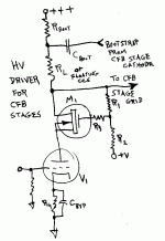
A HV driver idea (using a HV Mosfet cascode with N Fdbk) for these CFB type designs:
(12HL7 could be triode wired for the bottom triode to get high gm, or E55L/8233 for $$$)
The RL could be replaced with a floating CCS. ( CCS only has to handle the small difference between the bootstrap and the output drive signal)
(12HL7 could be triode wired for the bottom triode to get high gm, or E55L/8233 for $$$)
The RL could be replaced with a floating CCS. ( CCS only has to handle the small difference between the bootstrap and the output drive signal)
Attachments
Last edited:
The tube is feeding into a higher impedance
with the mosfet making it much more effective. I feed the 12Ax7s into a fet because the 12ax7 is very weak as a driver but a wonderful voltage amp and it loves seeing that high impedance so it can loaf.
A HV driver idea (using a HV Mosfet cascode with N Fdbk) for these CFB type designs:
(12HL7 could be triode wired for the bottom triode to get high gm, or E55L/8233 for $$$)
The RL could be replaced with a floating CCS. ( CCS only has to handle the small difference between the bootstrap and the output drive signal)
with the mosfet making it much more effective. I feed the 12Ax7s into a fet because the 12ax7 is very weak as a driver but a wonderful voltage amp and it loves seeing that high impedance so it can loaf.
I'm sorry it might have been a Sowter?
I love vanderveens trafos but I wish they were cheaper..LOL
I don't know of a Lundahl UC transformer. At the time I built my amp, I was considering building something with one of their transformers but I don't remember seeing a UC transformer.
My UC transformers are toroids and were designed by Menno Van der Veen. I did send a message through Plitron to him and let him know I wanted a lower-impedance version. He sent a message back that that transformer was a lot of work to design and he probably wouldn't be doing any more UC transformer designs. That was years ago, though.
I love vanderveens trafos but I wish they were cheaper..LOL
It's quite detailed and you may have seen this but it gets into some specifics
http://www.tubebooks.org/books/lockhart.pdf
Sylvania came up with the same link in post #76 🙄
What happened to Sylvania anyway?
Looks like he checked out permanently. "Account disabled at member's request"
Or some hacker did him in.
Looks like he checked out permanently. "Account disabled at member's request"
Or some hacker did him in.
I didn't know you live in NC
I love it down there especially being a huge NASCAR fan. I'm going to Charlotte for a convention in three months.
What happened to Sylvania anyway?
Looks like he checked out permanently. "Account disabled at member's request"
Or some hacker did him in.
I love it down there especially being a huge NASCAR fan. I'm going to Charlotte for a convention in three months.
I'm over in Hickory, about an hour away from Charlotte. If you are driving down, stop by. (send a message ahead)
Can't say that I am a fan of Nascar though. We do have a racetrack in Hickory. But the only benefit I can see is lots of vehicles driving around without mufflers here.
Can't say that I am a fan of Nascar though. We do have a racetrack in Hickory. But the only benefit I can see is lots of vehicles driving around without mufflers here.
I'm over in Hickory, about an hour away from Charlotte. If you are driving down, stop by. (send a message ahead)
Can't say that I am a fan of Nascar though. We do have a racetrack in Hickory. But the only benefit I can see is lots of vehicles driving around without mufflers here.
I actually teach automotive electronics and emssions commonly called drivability but in spring I teach the drive lines and automatics class..We are meeting with NATEF that influences our course structure and we are trying to lobby to extend the course beyond 6 weeks when it used to be 8 weeks and that was before we had the later technologies fall into the equation.When it was just mechanical apparatus and hydraulics,they allowed the course to be taught in 8 weeks but now that we have solonoid control and electronic data which we have to convey,they said we need only 6 weeks.Go figure.Anyway I hope we have some success..I would love to stop by..I may have a rented car so that can work out.
Automotive electronics!
I do all my own repair work on my (old!) cars here. I'd be curious what is being taught in technical school (I suppose that's where) these days. Used to be in my generation that most guys could fix their car. Now I hardly see anyone that knows much about it. They all have expensive sports cars if they can afford them, but can't fix a headlight.
I suppose the computerized engine and transmission controls may have scared them all off, but I've found that stuff actually makes finding the problem easier in many cases. Just query the computer error codes. With one really old car (89 Maxima) I'm not afraid to try any repair (it still runs great). Great learning experience. I used to help my father with his cars, that's how I learned. The one thing I fear though is the cramming of the engine compartment with more and more stuff.
Accessibility has gone to H_ll. I'd hate to have to deal with one of the new hybrid cars. Talk about scary tube amp voltages and crammed up compartments. A friend of mine had a headlight go out on his Prius, and it cost him $700 to get it replaced at the dealer. No space to get to it. They had to remove the bumper first. Then there are all the buttons on the steering wheel these days for controlling everything. I have trouble just keeping the horn working on the old cars. Dirty slip rings. I asked a salesman about how the new Honda handled all those buttons on the wheel. Wi-Fi... I hope not! Terrorists will have a field day.
Last edited:
- Status
- Not open for further replies.
- Home
- Amplifiers
- Tubes / Valves
- MC275 OPT manual rewinding