Hi,
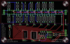
Could the experts comment/check on my relay input/volume controller. It's based on this design RelaiXedPassive
It'll be powered by a Salas's regulator and driven by an arduino nano.
The relay drivers are the Ti DRV777; I couldn't find the correct parts in Eagle so I've used the ULN2003A (which has the same pin-outs).
The left ground plane is the digital one and the right one is the analog. Otherwise I'm not really happy about the bottom power line which crossed the output; I'm not sure if it's critical or not.
I've never done any layout which includes SMD so I'm not sure if the "via" are correct for the connection to the ground plane.


Cheers,
Ced.
Could the experts comment/check on my relay input/volume controller. It's based on this design RelaiXedPassive
It'll be powered by a Salas's regulator and driven by an arduino nano.
The relay drivers are the Ti DRV777; I couldn't find the correct parts in Eagle so I've used the ULN2003A (which has the same pin-outs).
The left ground plane is the digital one and the right one is the analog. Otherwise I'm not really happy about the bottom power line which crossed the output; I'm not sure if it's critical or not.
I've never done any layout which includes SMD so I'm not sure if the "via" are correct for the connection to the ground plane.
Cheers,
Ced.
Last edited:
I have some questions...
It's a good start but I think you can reduce the amount of components, use more SMD and then improve the layout a lot 🙂
- Why choose DRV777 over the standard ULN2xxx? Does that device have a lower voltage drop?
- What are all those caps across the relay drivers for? and why have resistors between your MCP23xx and the relay drivers? One of the main points of using a relay driver is to reduce components!
- What size are the attenuation resistors? They look bigger than 1206.
- Your relays will draw a fair amount of current when all switched simultaneously. I would add an electro cap to your design, something like 100-470uF.
- Why use a Salas regulator? Non of the power from this design will touch the audio so you could use a cheap/small 7805 regulator and it would make no difference.
It's a good start but I think you can reduce the amount of components, use more SMD and then improve the layout a lot 🙂
Hi Max,
Yes the voltage drop is minimal. For a 5V power supply and 5V relays; the ULN2003 drops 0.9V.
I don't know about the caps across the drivers; they were in the original design that I've "badly" copied...
For the 4K7 resistors; apparently to reduce noise, here is the quote from the datasheet:
"DRV777 features an input RC snubber that helps prevent spurious switching in noisy environment. Connect an external 1kΩ to 5kΩ resistor in series with the input to further enhance DRV777’s noise tolerance."
I was planning to use it for powering the arduino, the input/volume, LCD and digital inputs switching. ...and I've got 3 spared/unused Salas's pcbs and I don't have to design/tweak/test/etc. my own regulator...
I was planning to have the ICs in SMD (the DRV777 are only in this package) and the rest in through holes (seriously I've never done SMD and the board so far is only 6.5cm x 7cm).
Otherwise to improve the analog ground plane, should I do a kind of reverse U shape to skip the power supply line on the relays pins? Additionally I could have 2 connectors (left and right) for the output so I don't have to cross the bottom power line?
I have some questions...
[*]Why choose DRV777 over the standard ULN2xxx? Does that device have a lower voltage drop?
Yes the voltage drop is minimal. For a 5V power supply and 5V relays; the ULN2003 drops 0.9V.
[*]What are all those caps across the relay drivers for? and why have resistors between your MCP23xx and the relay drivers? One of the main points of using a relay driver is to reduce components!
I don't know about the caps across the drivers; they were in the original design that I've "badly" copied...
For the 4K7 resistors; apparently to reduce noise, here is the quote from the datasheet:
"DRV777 features an input RC snubber that helps prevent spurious switching in noisy environment. Connect an external 1kΩ to 5kΩ resistor in series with the input to further enhance DRV777’s noise tolerance."
They are MELF resistors.[*]What size are the attenuation resistors? They look bigger than 1206.
Thanks, I'll add this cap.[*]Your relays will draw a fair amount of current when all switched simultaneously. I would add an electro cap to your design, something like 100-470uF.
[*]Why use a Salas regulator? Non of the power from this design will touch the audio so you could use a cheap/small 7805 regulator and it would make no difference.
I was planning to use it for powering the arduino, the input/volume, LCD and digital inputs switching. ...and I've got 3 spared/unused Salas's pcbs and I don't have to design/tweak/test/etc. my own regulator...
It's a good start but I think you can reduce the amount of components, use more SMD and then improve the layout a lot 🙂
I was planning to have the ICs in SMD (the DRV777 are only in this package) and the rest in through holes (seriously I've never done SMD and the board so far is only 6.5cm x 7cm).
Otherwise to improve the analog ground plane, should I do a kind of reverse U shape to skip the power supply line on the relays pins? Additionally I could have 2 connectors (left and right) for the output so I don't have to cross the bottom power line?
If I was you I would remove all those resistors and caps around the DRV777. You don't need them and don't care about noise because the power side of the relay will never touch the signal.
What size MELF are you using? I would use 1206 resistors as this gives you a much larger range of resistors to choose from. Including MMA0204 which fit on the same pads. Up to you though. I really recommend ensuring you can get the values you need in the package you are using before getting the PCB manufactured. There is a calculator here that can help:
The δ1 Relay-based R-2R Stereo Attenuator
Also, use the back side of the PCB for some traces. It doesn't need to be 100% solid ground plane and you can make your layout much better by running a few traces on the back. Look at the layout of the RelaiXedPassive as an example, see the power to the relays goes on the back. Also use solid ground planes on the top and bottom.
I hope that helps!
Make sure to add reverse biased diodes across each relay coil. When you turn them off, the stored magnetic field collapses, and you get a huge voltage spike, probably enough to pop the driver circuit. The Vishay MSE1PD is a very small SMD part, but should be sufficient to clamp the transient current. They're a little annoying to solder by hand, but not impossible. A standard 1N4002 or something like that is also OK if you want to use a through-hole part.
@maxw: I've updated the schematic and the pcb layout on my first post. The remaining things are; checking the size of the R2R resistor pads and then adding some mounting holes.
Good job, much better I think!
Some things you might want to consider, but not major:
- Run relay signal traces on the bottom too? Would be tidier.
- Perhaps have the spare I/O pins of the MCP23xx go to a pin header? You might want to use them later, like for a power relay or something.
Here's a couple of similar items that I made, with eagle files supplied:
http://www.diyaudio.com/forums/anal...-remote-volume-input-control.html#post3882944
http://www.diyaudio.com/forums/anal...i2c-relay-selector-attenuator-tube-stage.html
Here's one I made based on Max's files. I made only the attenuator (input section is separate) and went with mostly through-hole parts. Only done a very quick test so far, but it seems to work great.
Might be useful as inspiration (or as a warning 😉 )
/U.
Might be useful as inspiration (or as a warning 😉 )
/U.
Attachments
Hi
Hi guys,
This is partially connected to this thread.
Just to let you know that I was searching for remote control for my preamp project and could not find nothing decent looking. The one I found was minimum order of 10 pcs. On the end I ordered 10 pcs for approximately $200.00 CND with shipping and customs.
I am kipping few, soled few and still have few left.
It has 6 buttons and looks respectful. If anybody is looking for remote like that you can see it here :
6 Buttons NEW IR Learning Remote Perfect FOR Arduino Preamp AND Other Projects | eBay
Hope this is not against forum policy. I remembered how hard it was to fined appropriate remote control not powered by button batteries.
You must never have a circuit route that passes across a cut, or gap in a ground plane.Hi,
Could the experts comment/check on my relay input/volume controller. It's based on this design RelaiXedPassive
It'll be powered by a Salas's regulator and driven by an arduino nano.
The relay drivers are the Ti DRV777; I couldn't find the correct parts in Eagle so I've used the ULN2003A (which has the same pin-outs).
The left ground plane is the digital one and the right one is the analog. Otherwise I'm not really happy about the bottom power line which crossed the output; I'm not sure if it's critical or not.
I've never done any layout which includes SMD so I'm not sure if the "via" are correct for the connection to the ground plane.
Cheers,
Ced.
You must never have a circuit route that passes across a cut, or gap in a ground plane.
Why? This isn't 5GHz here - these are some relay control lines. Would one care about the characteristic impedance of those lines changing over the ground plane discontinuity?
Aside from controlled impedance lines, which is a fools errand anyway on a 2 layer board, why follow this rule?
My suggestion would be to line up the input relays with the connector pitch of the input jacks. There's no need to cram the relays next to each other. In fact, some relays with goofy magnetic systems can influence each other when spaced closely, so it's actually desirable to put some space between the coils. Beyond that, you're asking for dimensional tolerance problems, or some situation where a replacement relay can't be used because it's 1mm wider than the original and won't fit.
Also, I didn't look up those relays, but do they have the suppressor diodes built in? Make sure the part has them - it'd be slightly annoying to add them to your current layout.
The traces from pins 5 and 6 of IC1 run very close to each other. Even out the spacing among all of those lines, in case your boards get made really poorly and they have a risk of becoming the same trace. You don't have to use the pad pitch of IC2 to space these traces - you can add a bend in the traces after they fan out from IC2.
Try to center the traces passing between the resistor pads in the ladder. If you have solder mask, then this will be OK as is, but simply routing them centrally between the adjacent pads will prevent headaches in any case. Also, someone might work on the board later, scratch up the soldermask, and now you have a problem.
In general, it's good to have minimum clearances, and use this uniformly. No reason to have near minimum spacing on anything, unless you absolutely must.
Thanks for the comments but I've started this thread in 2014. I've already manufactured the board with oshpark and everything passed their pcb rules.
I've resurrected this pre-amp last month (been collected dust on my desk unpopulated); I'm currently testing the arduino connection. The multiplexer and the relay drivers are working I think.
Need to order the relays and the melf. I hope this time I'll finish completely this prototype!
I've resurrected this pre-amp last month (been collected dust on my desk unpopulated); I'm currently testing the arduino connection. The multiplexer and the relay drivers are working I think.
Need to order the relays and the melf. I hope this time I'll finish completely this prototype!
- Status
- Not open for further replies.
- Home
- Source & Line
- Analog Line Level
- another relay input/volume controller