Hello friends.
I'm looking to build a new amplifier.
I'm looking to build an amp with the following caracteristics.
- Bipolar transistor technology technology
- Less than 50w per channel
- Low part count as possible
- Powered from 9 to 16v
- Class AB design only
- Good for full range speakers and not only for subwoofers
If there is a PCW layout already made, that would be very welcome.
Who's interested in joining the team?
would be nice to see this develop and having people building all this amp that must exist somewhere but no one seems to find.
Thank you in advance.
I'm looking to build a new amplifier.
From a single 16V supply, you're only going to get about 3W into 8 Ohms.
You mean discrete transistors? 2 Watt Amplifier
Last edited:
Looking for a 90's class ab car amp ? They boost the 9-16v to +/-35v for @50w
per channel.
Any flavor amp on the forum will then work.
OS
per channel.
Any flavor amp on the forum will then work.
OS
9 -16V supply for a Class AB amplifier means quite low power unless the techniques used in early car radio chipamps (e.g. TDA20XX series IC) or bridging are applied. If a few watts is otherwise OK, you could consider some of the grossly overpowered headphone amplifier designs now everywhere.
I think many of the myriad desktop sound systems from the past 15 years would be covered by your spec, though I doubt actual subwoofers would. Maybe just modest woofers 😀
If you raised the bar to +/15V or a 30V supply, I think you may reach your goal a lot easier and open up the possibilities for many DIY designs that could be used as-is or adapted to the lower voltage without problems. If you want to use an existing wall-wart, you may find it just as easy to use a typical 19-23V laptop supply.
I'm looking for a small footprint, simple layout, low cost and low power amp.
The chip amp designs are not interesting and not much to learn from them. Besides, you keep depending on that specific IC, so I'm not the greatest fan for IC chip amps for DIY fun but I know that they have very good performance sometimes.
Many of us have already 12v laying around and also this voltage around the house is shared with the car and motorbike so I tend to think that whatever we do in 12v is very versatile and future proof.
If this amp is small enough maybe it can share an enclosure with something else.
Imagine a battery charger that gives music while it charges for example. It shares the 12v supply and enclosure for example.
A car amp design is a good option but I'm looking to make things even more simple.
Any squematic to discuss options to start with?
Any specific one you would recomend?
I'll upload the one I?ve been prototyping tomorow.
You say 'lowest part count possible' but disregard chipamps?
I have a chipamp design on my blog (link to the left of this post) - it fits your bill on supply voltage. There's a schematic but no PCB is available.
I do disagree there's nothing much to learn from playing with chipamps - from mine I learned the most important aspect of an amp is its power supply, in terms of listening satisfaction.
Ok, let's see:Hello friends.
I'm looking to build a new amplifier.
I'm looking to build an amp with the following caracteristics.
- Bipolar transistor technology technology
- Less than 50w per channel
- Low part count as possible
- Powered from 9 to 16v
- Class AB design only
- Good for full range speakers and not only for subwoofers
If there is a PCW layout already made, that would be very welcome.
Who's interested in joining the team?
would be nice to see this develop and having people building all this amp that must exist somewhere but no one seems to find.
Thank you in advance.
Mini-box 2W Amplifier - RED - Page33
or:
An externally hosted image should be here but it was not working when we last tested it.
I used the chipamp as a recognized topology example to detail what was necessary to get more than just a few watts from 12V systems. You can play with discrete parts in minimalist designs as you wish, understanding their power limitations, particularly at bass frequencies which require a greater amount of power by far.
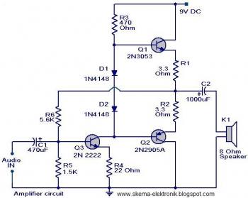
What's your minimum acceptable power? If you want to drive a subwoofer, you will need more power than a discrete amp can supply with a 12V supply. A 4R speaker system will be better, but only 3 dB better. Try any amplifier that can operate from a single supply and listen for yourself. Here's an example of a cheap and simple, minimal discrete design. Note that such circuits have poor power supply noise rejection, so even with the supply filtering components shown, a clean DC supply is advisable - not a crude battery charger.
You want simple? No problem - just a matter of how low you can go on performance as JMF showed you above.
Mini-box 2W Amplifier - RED - Page33
Hello again!
This is all very nice!
Thank you all for the sugestions.
Its great to see people picking this subject to cooperate and exchange thoughts on the matter.
The point of the situation is that I have my amplifier working now. 😀
At the moment for testing purposes I'm using an 80w 15.5v power supply.
The amplifier I built is the one mentioned on this video:
youtube.com/watch?v=-fIpj2eHL0k
The version I built is different because of the supply voltage and also because I use different transistors.
For 2n3904 ------- I use ---- MJL15032 ---- NPN
For 2n3053 ------- I use ---- D718 ---- NPN
For 2n905a ------- I use ---- B688 ---- PNP
I'm playing with resistor and capacitor values at the moment to see what I get but for the moment I do have a clean...ish sound.
So, the closest to what I am building is the second amplifier posted by JMFahey
What do you guys think of this second amplifier he posted?
I'll keep you posted on sound improvements (or no improvements)
Thank you
Given the 9-16V power supply, something using common emitter outputs would make sense. The old PW Texan amplifier would be a good starting point
And because with 12V supply, most of our listening is "in" clipping condition, it is necessary to design the amp to clip gracefully like tube amps.
And because with 12V supply, most of our listening is "in" clipping condition, it is necessary to design the amp to clip gracefully like tube amps.
I didn't know that.
So what is the minimum voltage so that it does not clip ?
The current status of my built is that my new little amp favours beats and lower frequencies. It feels like it needs to open up the top end and the higher midrange. Its also a lot more powerfull than I would have imagined. the part count is only 10 components.
If I can not improve this situation it won't go forward. I hope I can debug this considering it has all the caracteristics I could hope for so far except it is not full range amplification at the moment. I would say I have something near 8w (feels like it, maybe I'm wrong) it does not heat up that much, just spot on at 50cº and low cost, AB, and all that.
So only one problem remains to solve, the full range frequencies need to appear some how.
Any thoughts or ideas?
So, the latest developments are simple and good.
I've removed the electrolytic from the signal input and placed a polyester 4.7uf in parallel with the signal input. This was a great move because it no longer sounds so focussed on lower frequencies.
Like I was expecting, I wouldn't learn this much with a chipamp.
Sound quality is now at a nice volume, quality, clean, full range (but can still improve).
I'll have to break in this amp later on once I settle on one design.
Next I will try to place more capacitance near the transistors and one bleed resistor. I'll have to check a new layout and the best way to do this.
So far its going forward and as I knew 12v amplifiers can still perform great at low volume levels.
If I could make this mono amplifier 10w a stereo would be 20w and now that's something we can live with in many environments like offices or something.
I'm also sure this amplifier will sound 200% better once this starts to play with a linear power supply later on. For now its only connected to my switching power supply for testing purposes.🙂
Anyone interested in building this weekend project that has so much potential, low cost and simplicity?
I didn't know that.
Just my (personal) finding.
So what is the minimum voltage so that it does not clip ?
Very high. Music contains short term dynamics...
I would say I have something near 8w (feels like it, maybe I'm wrong)
Short term, why not. Depends on load impedance. 8 Ohm is idealistic and rarely the case. Usually it is much lower and can produce quite big power, as long as the power supply (and the heat sink) permits it.
So only one problem remains to solve, the full range frequencies need to appear some how. Any thoughts or ideas?
The common trade-off for bandwidth/speed is stability. I prefer to choose quality transistors first, then work out the surrounding components to support those transistors. High speed network requires compensation schemes and good layout, wiring and power supply.
For small supply voltage, it is preferable to use low Vce transistors because they have better performance in speed, capacitance, etc., without having to purchase expensive parts. Small output transistors (TIPs are cheap) are usually better than 2N3055.
Be careful with high capacitance cheap capacitors. You need small ones (or quality ones) to perform well at HF. Yes, local bypass (with good cap) is the trick.
It seems from the video that you are only talking about half-watt power or less and definitely not hi-fi. Kidstuff, but there's nothing wrong with experimenting if it's going somewhere with lasting benefits. Even so, there are better, faster ways to learn the basics of audio electronics than just playing with parts in a random fashion.So, the latest developments are simple and good.
I've removed the electrolytic from the signal input and placed a polyester 4.7uf in parallel with the signal input. This was a great move because it no longer sounds so focussed on lower frequencies.
Like I was expecting, I wouldn't learn this much with a chipamp......
If you are going to comment on what you are doing and expect replies, you need to post exact circuits - schematics - of what you are doing, either drawn clearly and scanned or made in a free drawing or simulation program that has exportable files. Otherwise, you are just telling a story about having fun but nobody can know with certainty what you are doing and to what circuit. With low power circuits, you may be safe from doing damage but when the power is a little higher and more useful, parts that are wrongly fitted or used in a bad circuit, start to burn. You soon build up a pile of dead parts.
You can do a lot of bad stuff that "works" without damage at low power but in your words - you don't learn much. Most arrangements of parts work or do something after a fashion at low voltage but that teaches you nothing about the reasons why real circuits or amplifiers work or fail or design methods to ensure they don't fail, either.
Take your time, check how practical power amplifiers work and make some notes from here: Amplifiers: Solid state amplifiers
This is the basics of the more powerful amplifiers we mostly discuss here but there are more topics and details for beginners there too. Look at the subjects index. Then go to the ESP website, to the "Beginners Luck" article section and start with a little more learning than happen-stance.
DIY Audio Articles That is a big site with forum and lots of serious educational and practical info, PCBs etc. 🙂
Last edited:
I assure you I'm not listening to half a watt while writing this with the little amp on right now. If you read carefully I am not using the same parts, circuit and power supply. That circuit is only the base of what I built.
I'll check out the articles you and sections you posted.
Thanks for taking the time to show some nice resources.
By the way, I haven't burnt or broken parts while experimenting with my amp, so don't worry too much.
I'm new to amp building but not to the game of audio or diy
About the squematic, I have been experimenting and once I'm confident that works nicely, I'll post it.
So far its burning in so I can listen better to it.
About the not learning much part, you know I was talking about chipamps so that is clearly out of context, I do am learning and thats what I said the first time.
I assure you I'm not listening to half a watt while writing this with the little amp on right now....If you read carefully I am not using the same parts, circuit and power supply. That circuit is only the base of what I built...
Then perhaps you can post the correct schematic and power supply details to give some meaning to what you claim, and by measuring the output voltage with a steady tone signal at say, 400Hz into a known load. You can use "Audacity" to generate that and an inexpensive DMM should work OK to measure AC voltage at that low frequency: Audacity®
Transistor substitutions don't alter the output of the amplifier other than to allow more current on demand into lower impedance loads but you need more or different speakers than you began with and a better (more current capability) design to do that. To increase power with a given speaker, you need a higher output voltage, readjustment of bias currents to suit and the amplification factor (determined by the negative feedback ratio) has to be increased. All that as well as higher rated, higher gain ourput semis. Obviously, that can't be detailed without the correct schematic and likely, an upgraded circuit that continues to perform well as the power is increased substantially to what - 10 times the original power rating?
I also think you are letting imagination take hold of your senses by saying your circuits need burning-in. Old or NOS electrolytic caps may need re-forming but there is nothing to burn-in. In my experience and in checking what others are actually talking about, "burning in" is most commonly the listener training themselves to tolerate audio system changes, distortion and other problems. It's actually counter-productive to do this, allowing any time at all between comparisons, if you are attempting to design something by listening only.
There is no context needed for "you don't learn much". It's an expression I borrowed from you in reply and simply acknowledged. Many exercises like electronic projects teach nothing without measurements and objective analysis. Without that in audio, we only have a subjective experience of some level of musical entertainment - or not, depending on expectations for sound quality, power, noise etc.
Please post or refer to the correct schematics, if you want to discuss design.
Finally, can you explain what you mean by "placed a 4.7uF polyester in parallel with the input" (that would short the signal input to ground). Do you mean "in series"?
Ok then.
Lets say I'll respectfully decline.
I'll keep this a hobby and some people want to change the mood of the thread and take things too seriously.
Thank you for all the support people, at least I reached my personal goal and the community got to share some interesting ideas.
As a hobby keeping things fun and interest is always the goal.
All hobbies exist only to make us feel good and put a smile on our faces.
On to the next project.....
- Status
- Not open for further replies.
- Home
- Amplifiers
- Solid State
- Any good 9v to 16v amplifier project?