Still no contact from Ostripper/ Pete for anyone?
Thimios,
What output devices are giving that output, certainly not the MT200 mosfet.
Thimios,
What output devices are giving that output, certainly not the MT200 mosfet.
Still no contact from Ostripper/ Pete for anyone?
Thimios,
What output devices are giving that output, certainly not the MT200 mosfet.
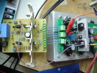
Output devices are NJW0281 NJW0302 .Thimios is testing with a Wolverine input which has no DC servo.
Yes IPS is the Wolverine,no DC servo not well matched inp. devices
Anyone who can measure the voltage across R113?
I can't remember the driver current and i must tweak this for +/-50v
And the value of R113
30mV offset is something expected for a non DC servo IPS.30mV output offset. Is the amplifier DC coupled?
AC coupled should allow much less than 30mVoff
Noise @ 200µVac is about 10dB to 20dB noisier than most amplifiers can achieve.
I expect <0.05mVac (50µVac) from all my amplifiers and try to find out why they can't and eliminate the error.
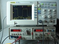
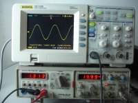
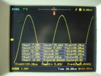
The last pic shows "CH1= 20.0V B"
What is that telling you/us about the clipping level shown on screen?
Noice=200μV is mine mistake .Is 200 μV reference to 200μV.😉
A new test using the <<Symmetry>> IPS
+\-50V
Idle current=30mA
Offset=-6mV
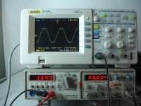
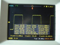
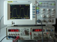
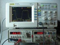
Vout=28V RMS/6R
Picture No 1 A.C out(inp schorted)
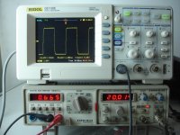
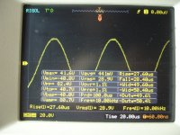
>> >> 2 D.C out >> >>
The rest on the pictures
+\-50V
Idle current=30mA
Offset=-6mV
Vout=28V RMS/6R
Picture No 1 A.C out(inp schorted)
>> >> 2 D.C out >> >>
The rest on the pictures
Attachments
-
 DSC09600.JPG601.7 KB · Views: 123
 -
 DSC09597.JPG601.3 KB · Views: 127
 -
 DSC09596.JPG622.9 KB · Views: 143
 -
 DSC09595.JPG560.5 KB · Views: 142
 -
 DSC09594.JPG548.6 KB · Views: 138
 -
 DSC09599.JPG571.8 KB · Views: 129
 -
 DSC09598.JPG525 KB · Views: 342
 -
 DSC09590.JPG600.3 KB · Views: 340
 -
 DSC09589.JPG583 KB · Views: 390
 -
 DSC09607.JPG573 KB · Views: 397
Last edited:
The rest
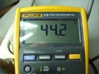
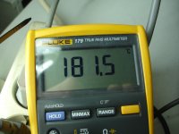
Picture No 7 load tempereture
>> >> 8 heatshing temp.
Picture No 7 load tempereture
>> >> 8 heatshing temp.
Attachments
Last edited:
Hello guys,
I decided to build the Slewmaster with Symasui IPS. I discovered the thread a few days ago and i am a little puzzled about this long thread.
For the Symasui i have 2 schematics. One from post#1628 and the other from Ostripper`s site.
1.Which one is good?
2.How do you adjust CCSadj?
For the Slewmaster:
1.What is the final variant?
2.How do you adjust Vbias?
3.What value should i choose for Csa/Csb?
I guess that these questions are already answered in the thread so sorry for repeating them.
Thank you!
Look here.http://www.diyaudio.com/forums/solid-state/248105-slewmaster-cfa-vs-vfa-rumble-841.html#post4420166Hello guys,
I decided to build the Slewmaster with Symasui IPS. I discovered the thread a few days ago and i am a little puzzled about this long thread.
For the Symasui i have 2 schematics. One from post#1628 and the other from Ostripper`s site.
1.Which one is good?
2.How do you adjust CCSadj?
For the Slewmaster:
1.What is the final variant?
2.How do you adjust Vbias?
3.What value should i choose for Csa/Csb?
I guess that these questions are already answered in the thread so sorry for repeating them.
Thank you!
#post 8410 is a list,i hope that will be useful
And the value of R113
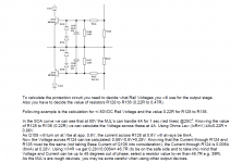
Across that resistor you will get approx 1,2V , divided by let me say 150R will give you approx 8mA. Bias is heating up small heatsik. With your psu voltage 100R or 68R should do the job. I am using 180R resistor there.
Regards
Peter
Thanks borys,the pcb that Gred has send to me, include 120R here,i have place here a 150R parallel so the result is 66R.Voltage across this combination (120R//150R)Across that resistor you will get approx 1,2V , divided by let me say 150R will give you approx 8mA. Bias is heating up small heatsik. With your psu voltage 100R or 68R should do the job. I am using 180R resistor there.
Regards
Peter
is 1.160V so the current is 17mA
A schematic diagram that i found show 20mA through this resistor.
Thanks borys,the pcb that Gred has send to me, include 120R here,i have place here a 150R parallel so the result is 66R.Voltage across this combination (120R//150R)
is 1.160V so the current is 17mA
A schematic diagram that i found show 20mA through this resistor.
I think Jason made some suggestions for this resistor in the build thread, but I haven't had a chance to find it yet.
Thanks Jeff, if you find this please report again.🙂I think Jason made some suggestions for this resistor in the build thread, but I haven't had a chance to find it yet.
The first problem is YOU have to learn how to size the various components.
The second problem is YOU have to find out what size of valid signal should pass to the load.
The third problem is YOU have to decide what size of load is no longer a valid audio load.
The second problem is YOU have to find out what size of valid signal should pass to the load.
The third problem is YOU have to decide what size of load is no longer a valid audio load.
how about adding a current limiter for the safe operation for the slewmaster OPS?
This kind of things, as well as forced air cooling, are important for professional stage-grade equipment, as it is used in close-to-the-limits manner during the long periods of time, clipping is not a surprise there, etc.
In the home system, having that much extra power and a good control/protection board, the limiter is just not needed.
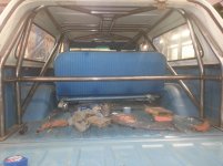
It's just like with cars. Safety cage, made of metal pipes, is a must for a rally car or a buggy - probability of rolling over is rather high, it's just normal thing for such a car. However, safety cage is never used in the normal consumer cars - or course certain measures to make the body harder is there, but rolling over is more like an incident 😉
This kind of things, as well as forced air cooling, are important for professional stage-grade equipment, as it is used in close-to-the-limits manner during the long periods of time, clipping is not a surprise there, etc.
In the home system, having that much extra power and a good control/protection board, the limiter is just not needed.
It's just like with cars. Safety cage, made of metal pipes, is a must for a rally car or a buggy - probability of rolling over is rather high, it's just normal thing for such a car. However, safety cage is never used in the normal consumer cars - or course certain measures to make the body harder is there, but rolling over is more like an incident 😉
Half the street toys I build have roll cages!😀
Attachments
Half the street toys I build have roll cages!😀
Just confirms the statement - this is definitely built for somebody who likes pushing the limits 😛 Looking great by the way

- Home
- Amplifiers
- Solid State
- Slewmaster - CFA vs. VFA "Rumble"