Hi everyone:
I am working on building a couple of Chipamp.com LM3886 dual mono amps. On one PSU PCB, I accidentally soldered in the large 10,000 uF cap off the board. That is, it is not sitting square on the board, but up from the board by 2 or 3 mm and crooked.
Im' told that desoldering one of these things can be very challenging without a rework station or some other more specialized gear or skills. If I leave the cap soldered in as is, is it likely to cause problems? I was wondering, for example, about susceptibility to vibration.
Thanks in advance for any help.
Provided the cap is in the right way around, you have no problems.
I assume this is a through hole component? If so, desoldering it is super easy (provided the PCB is single sided).
there are many ways you can do this including:
- "solder wick / braid"
- A "solder sucker" which comes in a wide range of variants from bulbs to syringe type things
- Simply heat the joint and work the part in or out.
If your PCB does NOT have plated through holes, I recommend you try the latter technique - as through hole parts are easy to get out again.
If your PCB does have plated through holes, I would just leave it as is unless this is really bugging you.
googlyone:
Yes, it's through-hole cap. How is it easy? I tried with desolder wick over and over and can never get the solder out of the hole itself.
Would it be a good idea to put something under the cap as a sort of shim?
Yes, it's through-hole cap. How is it easy? I tried with desolder wick over and over and can never get the solder out of the hole itself.
Would it be a good idea to put something under the cap as a sort of shim?
Hi,
I think you do not have to remove it. What you do it is heat the lead hole and push it a little and then do to the other side. Repeat the sequence until the capacitor it is completely seated. Sometime it happened to me and that it is the way I re-seat it. Also add rosin core when applying heat to the leads holes to increase the heat transfer to the capacitor lead.
I think you do not have to remove it. What you do it is heat the lead hole and push it a little and then do to the other side. Repeat the sequence until the capacitor it is completely seated. Sometime it happened to me and that it is the way I re-seat it. Also add rosin core when applying heat to the leads holes to increase the heat transfer to the capacitor lead.
tauro0221:
Thanks. To be honest, I've never been successful in doing such things. For one thing, it's hard with only two hands. I have a Panavise, but it doesn't work well on boards like this, cause it cuts too close to components which are very small and very close to the edge of the board.
Would a rework station work? How much heat can that Nichicon 10,000 uF handle before I damage it?
if it is plated through hole, just leave it.
with plated through holes it can be hard to melt the solder right through, and if there are large planes or tracks with poor thermal relief it can become very hard. Tauro's advice is good, but you might not be getting enough heat into the joint.
This is a common problem if:
- Your soldering iron is not wetted to the component lead / pad. and/or
- your soldering iron is not powerful enough to get the whole lot hot.
Capacitors are pretty tough - so you can have a play - but I suspect you are worried about something that is not relevant.
A small gap is no problem. Being somewhat crooked is no problem. Desoldering or remaking soldered joints always carries a risk, so why attempt something which can do no good and may do harm?
Hi,
I think he is looking for the aesthetic built of the project. Do you cross a bridge that it looks crooked?
I think he is looking for the aesthetic built of the project. Do you cross a bridge that it looks crooked?
A crooked bridge may be an unsafe bridge, because a bridge is essentially a mechanical item. A crooked capacitor is electrically the same as a straight capacitor, unless you are operating at UHF or microwave frequencies.
Hi everyone:
I am working on building a couple of Chipamp.com LM3886 dual mono amps. On one PSU PCB, I accidentally soldered in the large 10,000 uF cap off the board. That is, it is not sitting square on the board, but up from the board by 2 or 3 mm and crooked.
Im' told that desoldering one of these things can be very challenging without a rework station or some other more specialized gear or skills. If I leave the cap soldered in as is, is it likely to cause problems? I was wondering, for example, about susceptibility to vibration.
A crooked component on a PC card is one of the simplest things to correct, requiring as little as just an appropriately hot soldering iron. Things get harder if the cap has all its connections on one end and the holes in the PC card don't match the spacing if the cap leads.
In tough cases, you may need to use a standard or special PC board bench vise to hold the board which leaves you two hands free.

Hi,
I think he is looking for the aesthetic built of the project. Do you cross a bridge that it looks crooked?
Yes all the time, particularly if it is the only practical bridge to use.
I have a Panavise, with the "circuit board" head. However, I think the wide angle head might work better, because of reasons I gave above-the PCB head has a groove and that can damage items soldered close to the edges of boards.
So, I don't have to worry about the cap vibrating any more than if it were
flush with the board?
If not, then I'll just leave it as is.
So, I don't have to worry about the cap vibrating any more than if it were
flush with the board?
If not, then I'll just leave it as is.
I have a Panavise, with the "circuit board" head. However, I think the wide angle head might work better, because of reasons I gave above-the PCB head has a groove and that can damage items soldered close to the edges of boards.
So, I don't have to worry about the cap vibrating any more than if it were
flush with the board?
Don't get me wrong. I like all my end-mount caps to be kissing the circuit card. But I'm not going to do anything non-trivial to correct it.
If the leads and board don't match well enough for a good fit, that is a minor design problem. I admit it, I don't do a lot with concours quality circuit cards.
If not, then I'll just leave it as is.
Well, its probably not broken and as as they say.... ;-)
You don't really need any soldering at all.
Real problem is that a heavy capacitor 2mm away from the board can and will flex them with vibration and either break the leg or the soldered pad.
A shim was mentioned and not bad, but the preferred solution is to add some adhesive material, both to "glue" cap to board and, filling the void space, act as a shim and avoid wiggling either way.
Personally I squeeze some thick contact cement or silicone with tip applied to the slot edge, so some material goes un der the cap, between it and PCB.
Or at least draw a consistent bead all around it.
Hot glue can also be used, but results are not as good.
Here's an axial capacitor, but idea is the same, avoid destructive wiggling:
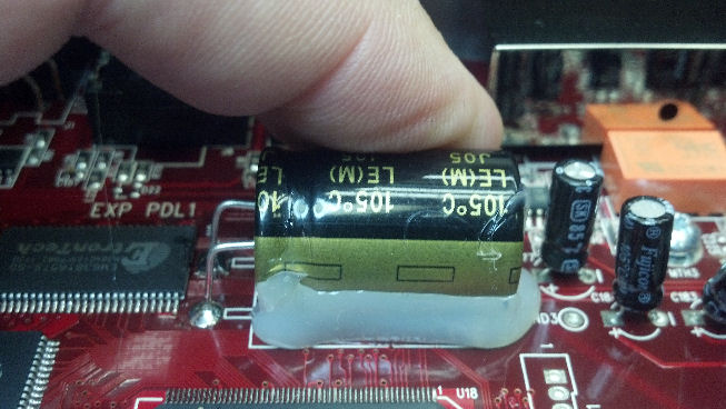
JMFahey:
Sorry, I don't understand that sentence. "The real problem is that a heavy capacitor 2mm away from the board will flex..."
Would you explain what you meant by that?
I follow fine the rest of what you said. Thanks.
Sorry, I don't understand that sentence. "The real problem is that a heavy capacitor 2mm away from the board will flex..."
Would you explain what you meant by that?
I follow fine the rest of what you said. Thanks.
Large capacitors not mechanically fastened to the PCB are a source of failure in older equipment. Over many heating/cooling cycles and power up/power down events, the solder holding the capacitor to the PCB becomes weakened. I have opened up old TV's and amplifiers where these "loose" large components (not only caps) are literally falling out of the board. A small dab of epoxy or caulking goes a long way at preventing these situations from ruining your day sometime in the future.
This is known as fatigue failure under cyclic stress. Slang term: rung out solder joints.
This is known as fatigue failure under cyclic stress. Slang term: rung out solder joints.
Hogwild: Tauro's advice is good. You don't need an extra hand, and forget using the panavise or any other implements. You just need your two hands and your soldering iron. If the capacitor stands proud of the rest of the components, simply rest the top of the capacitor on a solid surface. With your left hand hold the board horizontal. With the soldering iron in your right hand, melt the solder on one of the capacitor leads while applying a little downward pressure to the board with your left hand. This should move the lead through the hole a little bit; the capacitor will now be crooked. Melt the solder on the other lead, again while applying downward pressure. Repeat as many times as needed until the gap is closed up (probably just a couple of times for a 2mm gap). After this the solder joints may be a bit "dry" because some of the solder remains on the leads, so you may have to add a little more solder.
EDIT: Make sure the solder is good and melted, and don't apply too much pressure or apply it too early, otherwise you could lift the traces.
EDIT: Make sure the solder is good and melted, and don't apply too much pressure or apply it too early, otherwise you could lift the traces.
Last edited:
flex is to mean move. flex comes from flexible.JMFahey:
Sorry, I don't understand that sentence. "The real problem is that a heavy capacitor 2mm away from the board will flex..."
Would you explain what you meant by that?
I follow fine the rest of what you said. Thanks.
If a solid object moves (flexes) then the solid is subject to strain. Strain is a change in shape and usually length.
Repeated strain results in fatigue and ultimately cracking due to work hardening.
Cracking due to flex/strain/work hardening is probably the most common mechanical failure.
Caps like this should be flat to the board anything else is unacceptable and shabby workmanship, and also as pointed out likely to fail, the number one failing component in vibration testing is incorrectly secured large caps.....
- Status
- Not open for further replies.
- Home
- Design & Build
- Construction Tips
- Will large cap not square on PCB cause problems?