Hello. I have finally started assembling my SSE. I'm ready to install the IN4007 diodes and I'm not sure which way they go. The diodes have silver bands at one end and red tape on the leads on the same end.
The silkscreening on the board has white bands on the sides connecting to the rectifier socket.
Any help will be appreciated as to which way they go.
Thanks.
The silkscreening on the board has white bands on the sides connecting to the rectifier socket.
Any help will be appreciated as to which way they go.
Thanks.
Don't worry about the red tape. The band on the diode go to the band on the silkscreen.
Also verify that the banded (cathode) diode ends go to the positive filter capacitor terminal.
Also verify that the banded (cathode) diode ends go to the positive filter capacitor terminal.
Hmm. I don't remember installing those. I'm not using the D1 and D2 FREDs since I'm going with a tube rectifier.
Here are some photos.
Attachments

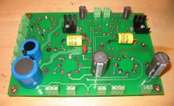
Hmm. I don't remember installing those. I'm not using the D1 and D2 FREDs since I'm going with a tube rectifier.
Here are some photos.
Just do as Bruce mentions in post #2 and you'll be okay.
Thank you!
Now, I have a favor to ask. Would someone mind posting a photo showing where they installed their CL-90? Or, maybe just a clear explanation of where it should go?
Thanks!
Now, I have a favor to ask. Would someone mind posting a photo showing where they installed their CL-90? Or, maybe just a clear explanation of where it should go?
Thanks!
Thank you!
Now, I have a favor to ask. Would someone mind posting a photo showing where they installed their CL-90? Or, maybe just a clear explanation of where it should go?
Thanks!
The CL90 would go on one of the two primary leads of your power transformer. Here's how -
From the live pin on your power input adaptor a wire is connected to one of the terminals on your power on switch.
The CL90 should be connected between the other terminal of the switch and one of the two primary leads of your
power transformer. The other primary lead should be connected to the N pin (neutral pin) on the power input adaptor.
You can use a piece of wire to connect from the power switch to one lead of the CL90 and other lead is connected to
one primary lead of your power transformer. Make the connections either by soldering or you can use a screw down
terminal with two slots.
Thank you spendorite.
I bought one of those all-in-one "receptacle/power switch/fuse holder" power entry modules.
My module has three solder terminals: L, N and Ground. So, I can install CL-90 between the Line terminal on the module and either one of the power transformer's black wires?
Thanks.
I bought one of those all-in-one "receptacle/power switch/fuse holder" power entry modules.
My module has three solder terminals: L, N and Ground. So, I can install CL-90 between the Line terminal on the module and either one of the power transformer's black wires?
Thanks.
Thank you spendorite.
I bought one of those all-in-one "receptacle/power switch/fuse holder" power entry modules.
My module has three solder terminals: L, N and Ground. So, I can install CL-90 between the Line terminal on the module and either one of the power transformer's black wires?
Thanks.
Yes, that's correct.
I have put in the CL-140 on the board beside the diodes but i did not get a Cl-90.
Does the Cl-140 do the same job or has it a different purpose?
Does the Cl-140 do the same job or has it a different purpose?
I have put in the CL-140 on the board beside the diodes but i did not get a Cl-90.
Does the Cl-140 do the same job or has it a different purpose?
Check this thread for an explanation..............
http://www.diyaudio.com/forums/tubelab/283196-tubelab-sse-inrush-optimal-setup.html
Check this thread for an explanation..............
http://www.diyaudio.com/forums/tubelab/283196-tubelab-sse-inrush-optimal-setup.html
Thank you!
- Status
- Not open for further replies.
- Home
- More Vendors...
- Tubelab
- IN4007 orientation (D3 and D4)