Hello to everyone. I'd like to undertake the built of the "Knight 10W 6V6 push-pull tube power amp".
As it is possible see looking at the schematic there is no info about the power transformer (so I can't calculate the required B+ with i.e. PSUD) and about the OPT.
Does anyone know the needed B+ of this power amp? Does anyone know a suitable output transformer?
Thanks.
As it is possible see looking at the schematic there is no info about the power transformer (so I can't calculate the required B+ with i.e. PSUD) and about the OPT.
Does anyone know the needed B+ of this power amp? Does anyone know a suitable output transformer?
Thanks.
Attachments

Last edited:
A 6v6 datasheet does give you the answer: between 8 and 10k Raa, dependent on your supply voltage. 20-25W power capability of the OPT is ok. If you go for Penthode, I would "stabilize" the G2 supply though. Alternatively, go after UL connection.
The 6v6 is nice also in a triode strapped push pull configuration.
Marcus
The 6v6 is nice also in a triode strapped push pull configuration.
Marcus
suggestion: pointz musical machine
http://www.diyaudio.com/forums/tubes-valves/149211-6v6-music-machine-build-help.html
http://www.diyaudio.com/forums/tubes-valves/149211-6v6-music-machine-build-help.html
Don't be tempted to put the mains supply and speaker connections on the same socket! They had different ideas about safety in the 1950s.
DF96, I forgot to mention that for safety reasons I will not connect the speaker as it is shown in the schematic. Anyway you are right thanks!
A 6v6 datasheet does give you the answer: between 8 and 10k Raa, dependent on your supply voltage. 20-25W power capability of the OPT is ok. If you go for Penthode, I would "stabilize" the G2 supply though. Alternatively, go after UL connection.
The 6v6 is nice also in a triode strapped push pull configuration.
Marcus
First of all thanks Marcus for the reply. Secondly, I searched on the net for a suitable OPT consider what you told me.
I found the 1609A OPT by Hammond (click here for specifications).
What do you think? All parameters you mentioned should be respected with it.
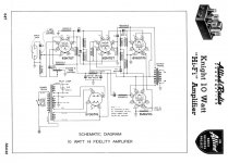
For clarification, this is the updated schematic (I will add a fuse too).
Instead of tweaking this old circuit, I would rather follow the recommendation of nicoch58 and look after poindexter's music machine - the old circuit might as well give you too much gain for today's audio sources.
As far as the opt is concerned, the 1609a works, you might want to consider the 1650e as well, bit low on impedance, but more iron for a (potentially) better bass response.
Marcus
Thanks Marcus for the reply. With regards the gain I need it because I will use the amp with my collection of 30's/40's electric coil pick-ups and with my 1954 record player. However, would you be so kind to explain me why the 1650e can give a better bass response? Seems that the the indicated RMS value is irrelevant when the it is greater than or equal to the indicated one by the amp schematic; am I right? And with regards to the impedance value, should it not be used the maximum value indicated for 6v6 tube (in this case 10k) in order to "be on the safe side"?
Please be patient, I'm a novice in the diy field.
Thank you again
Please be patient, I'm a novice in the diy field.
Thank you again
Last edited:
Hello again, can someone be so kind to tell me the needed B+ or the high voltage needed at the rectifier? And also can someone tell me the impedance needed at the primary of the OPT?
Supply voltage 270...300 V. Load resistance 8k.
See 6V6 specifications here: http://www.r-type.org/pdfs/6v6g.pdf
See 6V6 specifications here: http://www.r-type.org/pdfs/6v6g.pdf
6V6 max rated plate volts is 350V.
6V6 max rated screen volts is 315V.
The screen dictates the absolute maximum B+
A typical application of 6V6 push pull is 250V to 285V on the screen and the plate, with an output transformer of 8000 to 10000 Ohms.
The 5Y3 rectifier applications show a 10uF capacitor, not a 40uF cap (rather large).
The power supply is CRC, and does not have much ripple filtering.
For push pull, a good portion of the ripple is cancelled out because it is common mode on the output transformer. However, any imbalance of the tubes and transformer now appears as hum in the speaker.
You might use a 10uF input cap (easier on the 5Y3), then perhaps a 5 Henry choke, then the 40uF cap, followed by the resistor and the other 40uF cap.
This will have good ripple filtering, but will add weight and expense (choke).
Be sure to line up the choke and power transformer, so their fields do not introduce hum in the output transformer. Use 90 degree orientation relative to the output transformer, and put some space between them and the output transformer.
With about 45V drop on a 5Y3, about a 450V to a 470V Center Tap High Voltage secondary will give about 265VDC to 279VDC, including a 4V drop in the 10uF (middle of first ripple) and a 7V drop in the choke (100 Ohm DCR, and 70mA draw). You may have to adjust this some.
The old circuit uses (Shade?) feedback, similar RH SE amps feedback, only push pull feedback. Nice idea.
Looking at the 6V6 datasheet (bottom page 2), looks like 8000 Ohm primary Z and 285V B+ gives the lowest distortion and max power out. The 6V6 has slightly rounded plate curves (page 4 top), which usually means 3rd harmonic kicks up at higher primary Z.
(edit: I didn't see page 2 of the postings, Artosalo has the info already)
Tubes with straight plate curves can benefit from higher primary Z for low distortion. (like 21/6LG6 for example)
https://frank.pocnet.net/sheets/135/6/6V6GTA.pdf
https://frank.pocnet.net/sheets/123/6/6LG6.pdf
(edit: I didn't see page 2 of the postings, Artosalo has the info already)
Tubes with straight plate curves can benefit from higher primary Z for low distortion. (like 21/6LG6 for example)
https://frank.pocnet.net/sheets/135/6/6V6GTA.pdf
https://frank.pocnet.net/sheets/123/6/6LG6.pdf
FYI - If you happen to have an output xfmr for an EL84 amp, it should drop-in for the 6V6 amp. The two tubes (6V6 & EL84 / 6BQ5) are virtually interchangeable in these P-P AB circuits. But in most cases, the 6V6 shouldn't be run at the same maximum voltage as EL84 etc.
The old circuit uses (Shade?) feedback, similar RH SE amps feedback, only push pull feedback. Nice idea.
Actually not. Feedback is routed to driver cathodes, which is even more interesting.
BinaryMike,
Good point. Feedback is indeed to the cathode.
One thing that makes this feedback interesting is that it is from the output plates, not from the output transformer secondary. That eliminates the effect of leakage reactance to the secondary from affecting the feedback phase.
Good point. Feedback is indeed to the cathode.
One thing that makes this feedback interesting is that it is from the output plates, not from the output transformer secondary. That eliminates the effect of leakage reactance to the secondary from affecting the feedback phase.
Smoking-Amp,
Interesting about the 3rd harmonic Distortion, and primary Z.
The 6V6 has kinks in the plate curves from about 50 to 75V.
The 6LG6 does not have those kinks there.
A higher primary Z would allow the plate voltage to more easily to go down to the
voltages where the kinks are.
Interesting about the 3rd harmonic Distortion, and primary Z.
The 6V6 has kinks in the plate curves from about 50 to 75V.
The 6LG6 does not have those kinks there.
A higher primary Z would allow the plate voltage to more easily to go down to the
voltages where the kinks are.
The flatter plate curves would seem to allow better efficiency and lower distortion. Took me a long time to figure out why some tubes (pentode mode) had an optimum Zload instead of a monotonic optimum like triodes. But I am still puzzled that most of the more revered tubes DO have this plate curvature. Like 6BQ5, 6V6, 6L6.... Maybe some 3rd H is desirable for bass slam, especially if the OT is not quite up to it, I'm not sure what the explanation is really.
The "local" (excluding OT) N Fdbk to the driver tube cathodes (Knight schematic) would allow one to add in some negative resistance easily to cancel the OT winding resistance. Just split some of that 300 Ohm cathode bias resistor up for individual tube current sensing sent back to the driver cathodes (P Fdbks). As the outputs draw more current, the drive voltages would increase to make up for OT winding R losses. And a little inductance in the sense resistors would allow one to null out the OT leakage reactance as well. As long as its not overdone and turns into an oscillator anyway.
.
Last edited:
6V6 max rated plate volts is 350V.
6V6 max rated screen volts is 315V.
The screen dictates the absolute maximum B+
A typical application of 6V6 push pull is 250V to 285V on the screen and the plate, with an output transformer of 8000 to 10000 Ohms.
The 5Y3 rectifier applications show a 10uF capacitor, not a 40uF cap (rather large).
The power supply is CRC, and does not have much ripple filtering.
For push pull, a good portion of the ripple is cancelled out because it is common mode on the output transformer. However, any imbalance of the tubes and transformer now appears as hum in the speaker.
You might use a 10uF input cap (easier on the 5Y3), then perhaps a 5 Henry choke, then the 40uF cap, followed by the resistor and the other 40uF cap.
This will have good ripple filtering, but will add weight and expense (choke).
Be sure to line up the choke and power transformer, so their fields do not introduce hum in the output transformer. Use 90 degree orientation relative to the output transformer, and put some space between them and the output transformer.
With about 45V drop on a 5Y3, about a 450V to a 470V Center Tap High Voltage secondary will give about 265VDC to 279VDC, including a 4V drop in the 10uF (middle of first ripple) and a 7V drop in the choke (100 Ohm DCR, and 70mA draw). You may have to adjust this some.
The old circuit uses (Shade?) feedback, similar RH SE amps feedback, only push pull feedback. Nice idea.
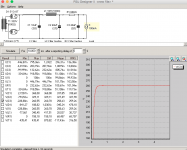
Thank you for the precise answer. Here attached are the results of two simulation with PSUD2. (using 10H choke).
Absorbing 70mA to 100mA we should stay in the specified range of voltage.
Any observation on the PSU? It could be fine? And any other suggestion for the rest of the amp circuit?
Attachments

- Status
- Not open for further replies.
- Home
- Amplifiers
- Tubes / Valves
- Knight 10W 6V6 push-pull tube power amp