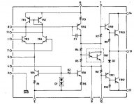
Got this amp thinking it’s one of Hitachi’s well-regarded MOSFETs power amps. Upon opening her up it was clear amp is not a MOSFET: the output stage is a quasi-complementary STK 4044V chip with two Darlington pairs but without any FETs.
This doesn’t mean it should sound bad; quasi-complementary discrete output stages were used in Marantz 22xx and some other amps of this era such as Sansui 5000 that sounded excellent.
The STK Darlington chips are high gain so it’s not surprisingly the amp at my bench test showed 153 WPC before clipping, both channels driven. The transformer in this thing is really huge, apparently capable of supplying enough juice.
The Hitachi was hooked to Nakamichi CA-7A preamp and Vandersteen 2CE sign speakers and it didn’t sound that bad; rather, it has a sonic signature of its own. Specifically, the lower midrange appears to be elevated, leading to slightly “boomy” bass. The soundstage is good but not as wide as my main power amp, the HK Cyt 12 MOSFET-modded 65 WPC. The upper midrange and high frequencies are there but again not as clear as Cyt 12. In this regard, sound is more “tubelike” that the MOSFET amp but lacking the “liquid midrange” tube amps have. Thus, the HMA-120 AV sound reminds me that of the unrestored Marantz 22XX and tube amps i.e. those with old caps and out of spec resistors.
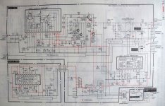
So I decided to improve the Hitachi first by recapping this babe, replacing wires going from speaker switch to terminals and replacing terminals themselves to high-quality 5-ways. Another thing I will try is to convert the amp to DC-coupled by removing input electrolytic cap (C701, 4.7 uF/50V) and another one in the negative feedback loop which I believe is C703 (100uF/6.3V) These mods are described here: http://www.diyaudio.com/forums/chip-amps/3500-stk-chips-2.html; look for posts of rljones esp. #5 and #20.
What do you guys think? Any advices on the subject or on STK amps in general are welcomed.
This doesn’t mean it should sound bad; quasi-complementary discrete output stages were used in Marantz 22xx and some other amps of this era such as Sansui 5000 that sounded excellent.
The STK Darlington chips are high gain so it’s not surprisingly the amp at my bench test showed 153 WPC before clipping, both channels driven. The transformer in this thing is really huge, apparently capable of supplying enough juice.
The Hitachi was hooked to Nakamichi CA-7A preamp and Vandersteen 2CE sign speakers and it didn’t sound that bad; rather, it has a sonic signature of its own. Specifically, the lower midrange appears to be elevated, leading to slightly “boomy” bass. The soundstage is good but not as wide as my main power amp, the HK Cyt 12 MOSFET-modded 65 WPC. The upper midrange and high frequencies are there but again not as clear as Cyt 12. In this regard, sound is more “tubelike” that the MOSFET amp but lacking the “liquid midrange” tube amps have. Thus, the HMA-120 AV sound reminds me that of the unrestored Marantz 22XX and tube amps i.e. those with old caps and out of spec resistors.
So I decided to improve the Hitachi first by recapping this babe, replacing wires going from speaker switch to terminals and replacing terminals themselves to high-quality 5-ways. Another thing I will try is to convert the amp to DC-coupled by removing input electrolytic cap (C701, 4.7 uF/50V) and another one in the negative feedback loop which I believe is C703 (100uF/6.3V) These mods are described here: http://www.diyaudio.com/forums/chip-amps/3500-stk-chips-2.html; look for posts of rljones esp. #5 and #20.
What do you guys think? Any advices on the subject or on STK amps in general are welcomed.
Attachments
Last edited:
Remove C703 and you will have DC offset issues!
Hmm, interesting. So you mean the rljones mod he described is not applicable here or it's just the wrong cap, not the one in the NFB loop?
Other thing I forgot to mention is adding a 200 pF cap between pin 13 ( output) and pin 3 (ground) of the STK to eliminate oscillation at low signal levels and decrease noise as rljones suggested. Could/should this be done here?
Examined the C703 role in DC offset. The voltage across the cap is 198 mV.
In the left channel the offset is -4 mV and jumping the C703L resulting in DC offset going to +28.4 mV. However, in right channel the offset is -28 mV and jumping C703R resulted in a brief surge of the offset to -1.57V then relay clicked and offset went to +31 mV.
I'll leave the C703 alone.
Found another thing in this amp which puzzles me: in several places, capacitors both 'lytics and ceramic of the identical values are connected in series. For example, C707-C709 are three ceramics caps 330 pF each in series; C718-C719 are 22uF/50 V electrolytes in series.
Why Hitachi did this, for circuit tuning of some sort or they just didn't want to use more expensive high-voltage single capacitors?
Looks like the latter. Doing this with electrolytics isn't the brightest idea, as varying leakage current means that voltage sharing is pretty random, more so in old age. When people have to do this, they'll normally include some parallel resistors to balance things out. Here I'd just put in a single cap (2x 22µ/50 --> ~10-22µ/100).
That what I suspected. I'll replace all caps in series, both electrolytics and ceramics, with smaller capacity/higher voltage equivalents. Ceramics will be changed to polystyrene; I have a few of high-voltage ones left from tube projects.
Looks like the latter. Doing this with electrolytics isn't the brightest idea, as varying leakage current means that voltage sharing is pretty random, more so in old age. When people have to do this, they'll normally include some parallel resistors to balance things out. Here I'd just put in a single cap (2x 22µ/50 --> ~10-22µ/100).
- Status
- Not open for further replies.